Dual-Band Transceiver for 1.3GHz and 2.3GHz bands
Iulian Rosu, YO3DAC / VA3IUL, http://www.qsl.net/va3iul
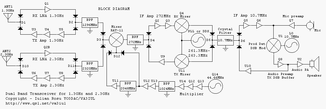
This is a low-power dual-band transceiver dedicated for 1.3GHz and 2.3GHz amateur bands, working in SSB and CW modes. Covered frequencies are 1296MHz to 1298MHz and 2320MHz to 2322MHz.
Schematic description
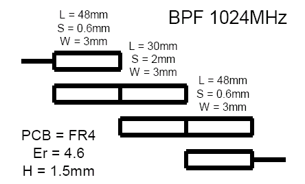
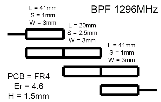
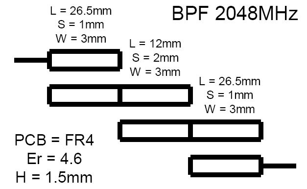
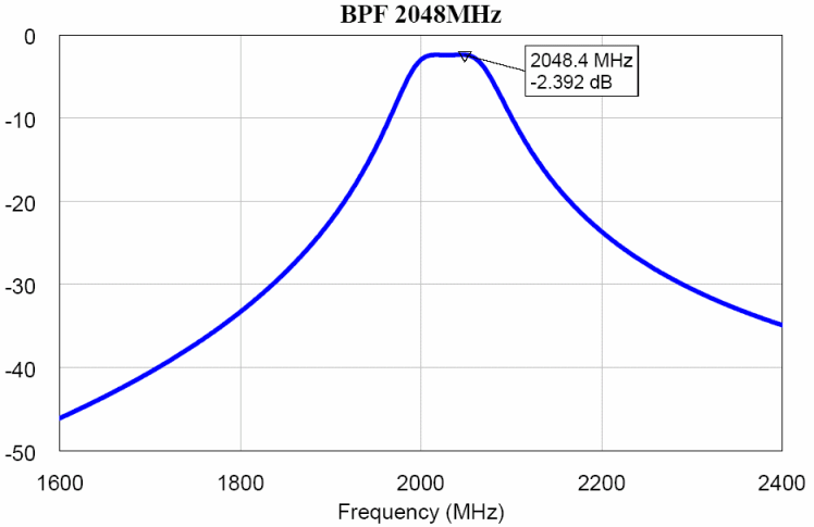
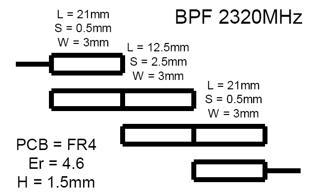
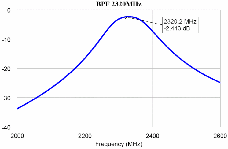
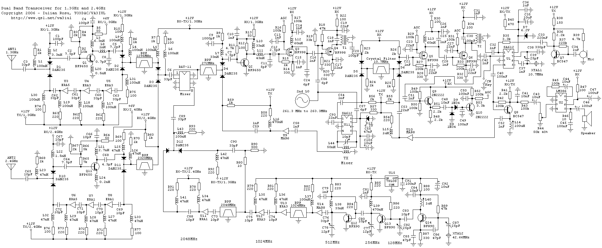
On the receive side the signal is amplified by two Low Noise Amplifiers (Q1 and Q11), one for each band. These are made using BFP650 Silicium-Germanium transistors. The gain of the LNA’s is around 14dB and the Noise Figure 1dB. After the LNA micro-strip Band Pass Filters it will filter the unwanted signals. The design of these filters requires a good knowledge of the PCB material properties (Er, thickness, etc). Even a small variation of these parameters will shift the center frequency of the filter, degrading the performances of the transceiver. All the filters are switched between RX and TX mode, using switching diodes (DAN235, or any other equivalent type).
First mixer is a Minicircuits RAY-11. This is the most expensive component of the transceiver but could be replaced by any other diode mixer that covers these frequencies.
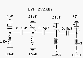
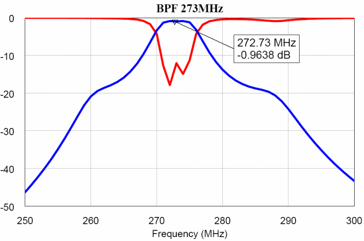
The frequency of the first IF is 272MHz. The reason this frequency was chosen is to simplify the design of the first LO. The 272MHz IF amplifier is using a BFP650 and a MOSFET BF998, controlled by AGC.
The frequency of the first LO for 1.3GHz band is 1024MHz, and for 2.3GHz band is 2048MHz, which is double of 1024MHz. Starting from the same crystal oscillator and using cascaded multipliers can feed the first mixer with signals from the same LO, but picking up the signal from different stages.
The RAY-11 mixer and first IF Band Pass Filter are switched between RX and TX modes using diodes (D3, D4).
Q2 and Q3 are the first IF amplifiers and second RX mixer is a dual-gate MOS transistor (Q4).
The second IF is 10.7MHz and there is done the main channel filtering using a Crystal Filter (BW = 3kHz). This filter is switched between RX and TX using diodes (D5 and D6). In SSB-TX mode this filter is used to suppress the unwanted side band and the residual carrier that remain after DSB modulation.
Q5 and Q6 are the second IF amplifiers, and they controlled by AGC.
U1 (SA612) has triple function. Is a Product Detector in RX mode, DSB modulator in TX mode and Beat Frequency Oscillator, using an external 10.7MHz crystal. Adjusting the C25 the frequency of the BFO can be set on the right position on the side of the Crystal Filter. Q8 has also double function, audio preamplifier in RX mode and DSB buffer in TX mode.
In TX mode the 10.7MHz SSB signal is filtered by the Crystal Filter and is amplified by U10. Following that the signal is translated to 272MHz using the mixer U11 (SA612).
Second LO used for translation between first and second IF is a PLL or a DDS covering frequencies from 261.3MHz to 263.3MHz. The schematic of this LO is not shown here. Myself I used a HF DDS (AD9850) upconverted to the desired frequency.
Block Diagram

Main schematic
Microstrip Filters
