144MHz All Mode Transceiver
Iulian Rosu, YO3DAC / VA3IUL, http://www.qsl.net/va3iul
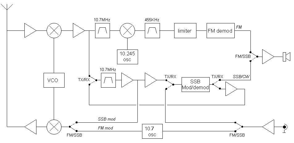
The main characteristic of the transceiver presented below is simplicity, but in the same time giving good performance, with a minimum investment. The radio is based on MC3362 (buy). This integrated circuit its an FM receiver, double conversion, which have inside almost everything that you need to build a radio. Starting with an RF amplifier and ending with an FM demodulator. Including a VCO up to 180MHz, LO for 10.245Khz, two mixers, IF amplifiers. Using T1 in the front-end the sensitivity will be 0.2uV/50ohms at the antenna port. On the RX path, the signal is amplified by T1 and foreword to the pin 1 of MC3362. The voltage control of the internal VCO is pin 23, voltage that must not be higher than Vcc of the MC3362, in our case +5V. The VCO voltage control could be given by a Phase Comparator part of a synthesizer, or could a tuning potentiometer. Of course, in the last case the frequency stability is not the best. At pin 20 of MC3362 (VCO out) we have 300mV of RF, enough to drive the TX mixer (gate 2 of T9). FM audio is on pin 13. From pin 19 we pick-up the signal for SSB and CW. The filter on this path is a 10.7MHz Crystal Filter. T5 and T6 are IF amplifiers. MC1496 (Digi-Key) is the product detector in RX and DSB balanced modulator in TX mode. For CW carrier this modulator becomes an unbalanced modulator using a DC voltage +TX/CW. The 10.7MHz crystal filter is used also in TX/SSB to attenuate one of the side bands. T5 is the carrier LO and T8 is the FM modulator. The 3W TX output is obtained using a BLX-65. For microphone amplifier we use an LF 356 and for audio power amplifier LM-386. The variable oscillator (synthesizer board) working in a range of 1 to 3 MHz. Using a 44.1MHz crystal (T15) we can select the third harmonic (132.3MHz) which is mixed with VCO signal, and become an RF signal in a range of 1 to 3MHz. This together with VFO output, are applied to the input of the Phase Comparator CD4046 (Digi-Key). The error voltage (pin 13 of CD4046) is the voltage control of the internal VCO of MC3362. To display the working frequency we can use the output of the VCO (pin 20 of MC3362) or VFO output (pin 10 CI-6).
I would recommend as a second choice, using the PLL syntesizer based on the project of AK2B which is using a Si5351 module (buy) module, an Arduino Nano, and an LCD display.
L1 = 5
turns, 5mm diam., 1mm copper wire silver plated,
L2 = 5 turns, 5mm diam., 1mm copper wire silver plated (side-by-side L1)
L3 = 5 turns, 5mm diam., 1mm copper wire silver plated (L3 is placed in separate
housing than L1 and L2)
L4 = 1 turn over L3
L5 = 470 nH, air core
L6 = 10 uH, ferrite core
L7 = 5 turns, 5mm diam., 1mm copper wire silver plated,
L8 = 5 turns, 5mm diam., 1mm copper wire silver plated (side-by-side L7)
L9 = 5 turns, 5mm diam., 1mm copper wire silver plated,
L10 = 3 turns, 5mm diam., 1mm copper wire silver plated,
L11 = 5 turns, 5mm diam., 1mm copper wire silver plated,
L12 = 3 turns, 5mm diam., 1mm copper wire silver plated,
L23 =
1mH, ferrite core
(L13,L14), (L15,L16), (L17,L18), (L19,L20), (L21,L22) = 10.7MHz IF can transformers
(usually with, primary 13 turns with 51pF in parallel, and secondary 2 turns).
For 10.7MHz IF cans check:
http://mediaserver.voxtechnologies.com/FileCache/Toko=RAN-10A6729EK=datasheet1-158257036.pdf
http://www.mouser.com/catalog/specsheets/XC-600131.pdf
Iulian Rosu, YO3DAC / VA3IUL
Home
http://www.qsl.net/va3iul
Iulian Rosu Iulian Rosu Iulian Rosu Iulian Rosu Iulian Rosu Iulian Rosu Iulian Rosu Iulian Rosu Iulian Rosu Iulian Rosu Iulian Rosu Iulian Rosu Iulian Rosu Iulian Rosu