A long time ago - I wanted to place little amplifier near the transceiver on my table. The main requirements was: power up to 500-600 W, momentary preparedness to work, minimum heating and noise. I have a very big experience in the different direction of the radio: this is amateur apparatus development. I understand - how the amplifier have to work and I fitted the tasks. Before - I built the amplifiers with glass bulbs, which have parameters as ceramic. The amplifiers with glass bulbs, usually not require additional cooling, but glass bulbs is too hot, when amplifier is in "STANDBY" position.
Ceramic bulbs - need to be blown necessarily! The cooling is realizing with blow out of the air - via heat sink of the bulbs - therefore air flowing should be very strong.
But strong airflow - produce a big noise. I built the amplifiers with metal/ceramic tubes: GS-35B, GS-1B, GI-7B, GU-74B (4CX800), 2xGU-74B (2x4CX800) so I know that problems. Metal/ceramic triode- GS-35B is very good for the amplifier. GS-35B has a big copper heat sink, which is easily can be blown. But the lamp has low steepness therefore it requires big entry power. In addition to this lack also a very high anodic voltage (not less than 3kV) and a big size of the bulb. Therefore such a lamp is not fitting for the small size of amplifier, with 500-600W of "out".
As a result of that - was my decision to create transistor amplifier.
The main - this amplifier have to provide maximum possible reliability. Because this is main lack of the transistor amplifier, compared with the tubes. This is also low efficiency of the transistor amplifiers, that sometimes not exceeded 50% - this also should be taken into account.
At my old constructions - I used all types of powerful transistors, which was produced by Soviet industry. Quality of those transistors - was too bad! Difference in parameters of this transistors - was very big. For choosing a few transistors with same characteristic (matched) - more than 10 items should be bought. So - reliability of amplifiers with power more than 300W was low.
Analysis of the amplifiers with power up to 500-600W, that is now producing for the radio-amateurs, showed, that the most popular transistors is MRF150 from Motorola.
Go to
http://www.communication-concepts.com - you can find there amplifier kit EB-104, which created for 4xMRF150 of transistors.
I sent my order and lot of messages to Communications Concepts, Inc. for 2 months, but nobody didn't answer and didn't send me my order - kit of amplifier EB-104 and kit of low Pass Filters for the EB-104.!
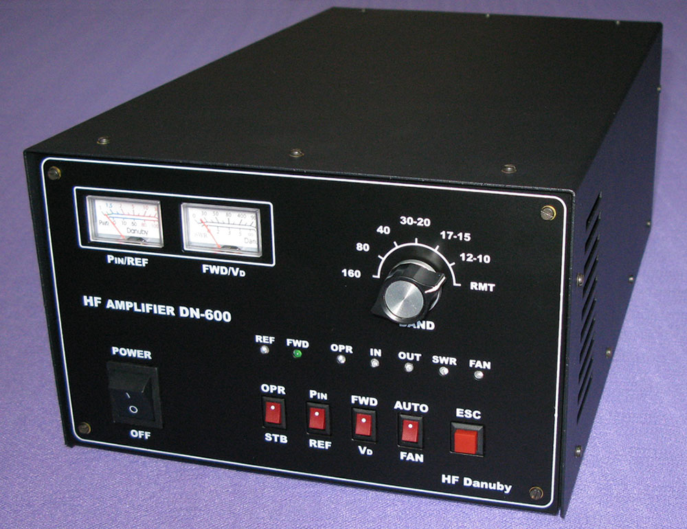
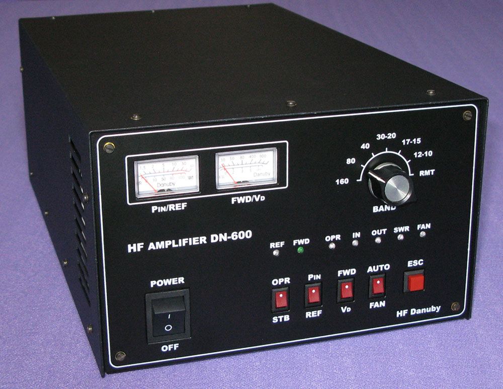
So - I have to build the amplifier by myself. My amplifier is similar to Ameritron ALS-600, or Tokyo Hy-Power HL1Kfx but with differences. I will write further about them.
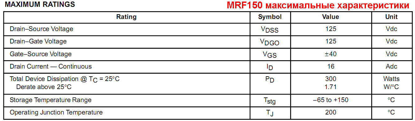
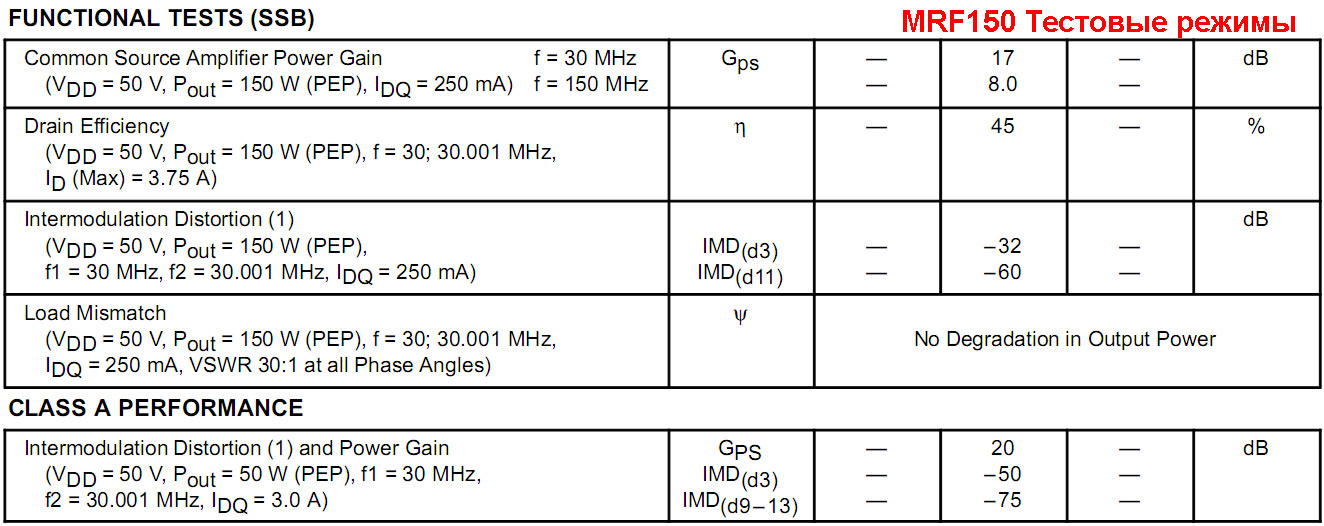
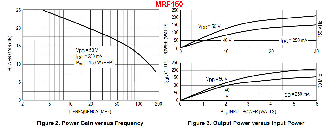
MRF150 transistors require voltage supply of 50V. Current up to 21-24A - this is needed for getting the output power in 500-600W. Easiest a way, to got the power supply ready for use - products from Mean Well http://www.meanwell.com. This is spread all over the world product and it has acceptable parameters for normal price. For our task power supply with power in 1000W for example SE-1000 of MW will be ok! This power supply has two
flaws:
1. It's have low noiseproof factor and can radiate QRM for receiver on frequency ranges 136kHz, 1.8MHz, 3.5MHz.
2. The small-size of fans with big RPM of turnings to supply enough air flow for cooling the elements inside the block, which company "MW" are install at this power supply.
These fans is very noisy. Therefore it's should be replaced with another ones, that will supply good airflow, but with less noise.
I.e.- if we want to get the amplifier with a small noise and minimal QRM to receiver - we should remake the power supply.
And while the producing this construction keep in mind attenuator and screening.
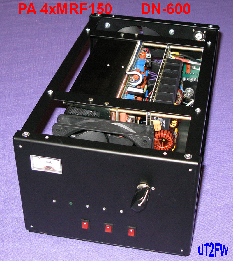
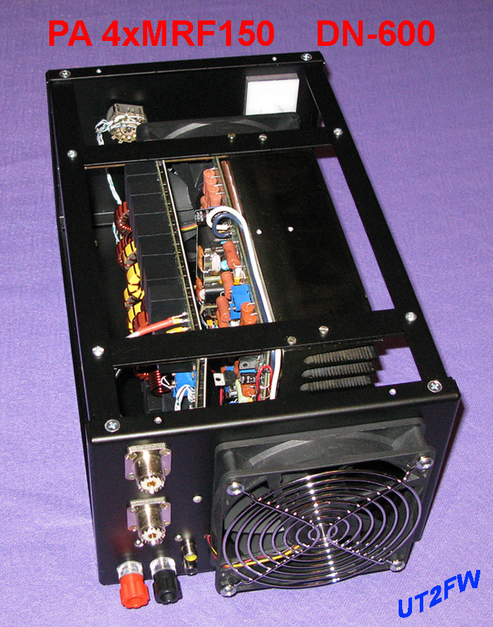
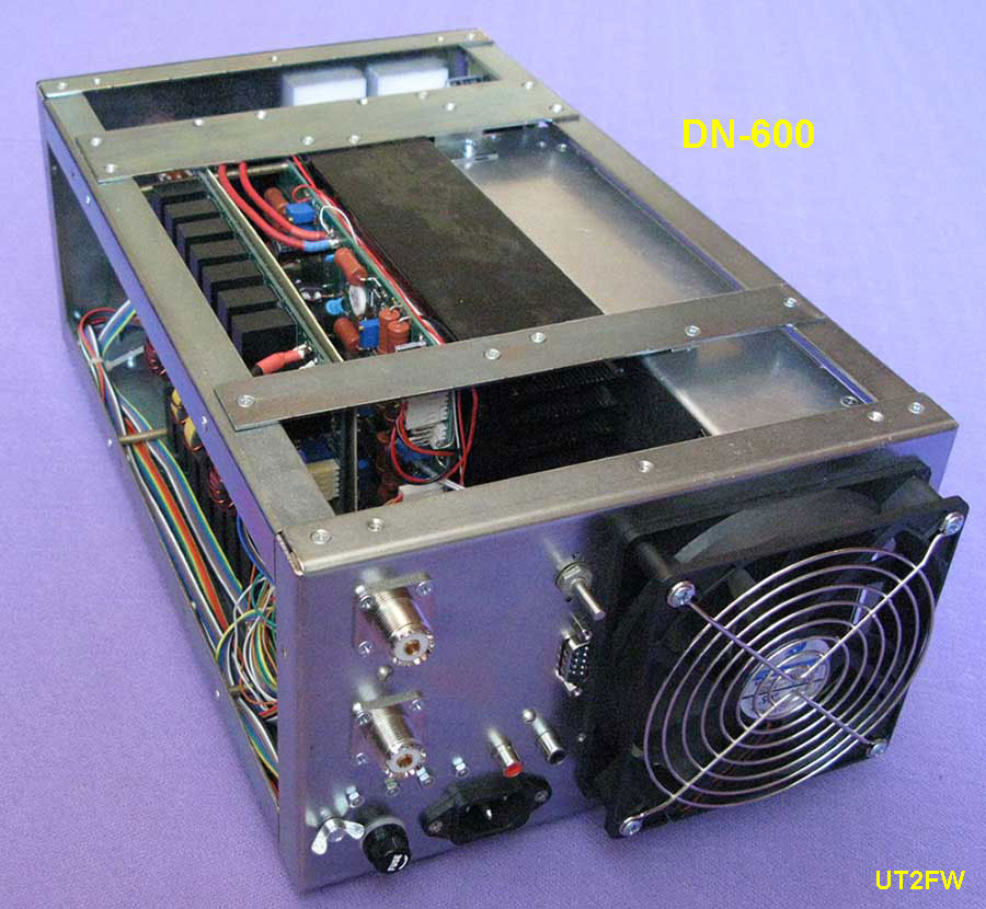
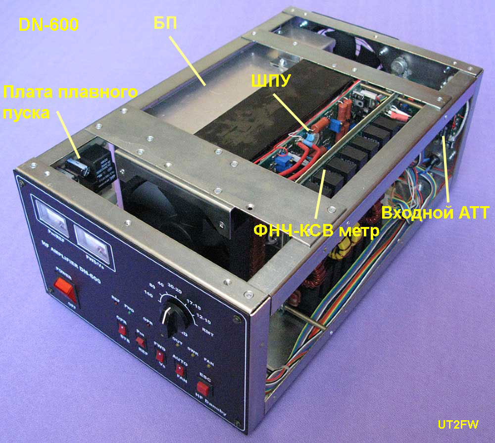
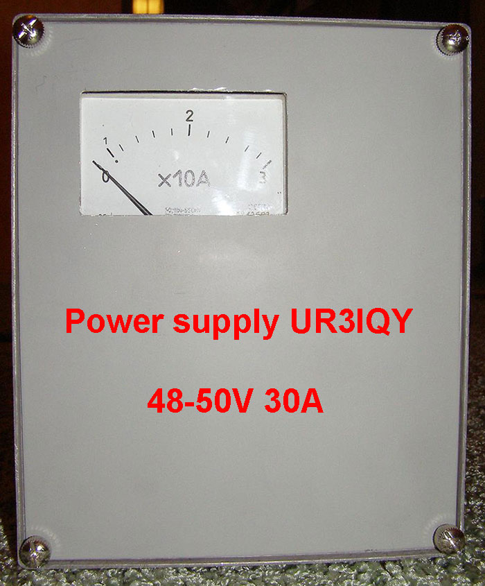
Variant of remaking the power supply for placing it inside of amplifier.
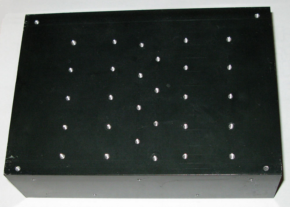
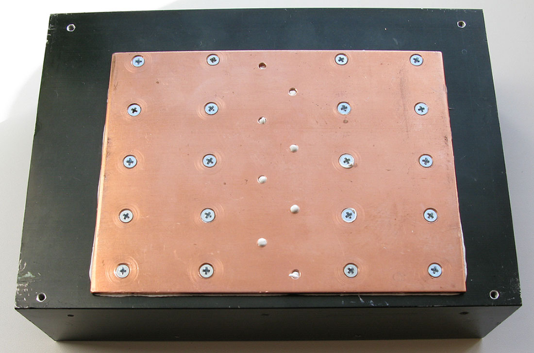
Carefully disassemble the block. Attention! Take look to the heat sink connection with the heat paste - must be one smooth layer. No any dust, or trash not to stick to the paste. Make sure, that there is a good heat contact between the cover and the heat sink through the paste. Just in this case - we will get maximum effect from heating transfer and connection with all corps of power supply and heat sink. We have to sawed off the side of the body, where fan will be installed. Plank with the ends should be unsoldered.
Layed wires should be unsoldered
If in the body of amplifier leave enough space for this placement, then contacts may not be removed. How to cool of the power supply? You can find the answer in section of "assembling of body amplifier".
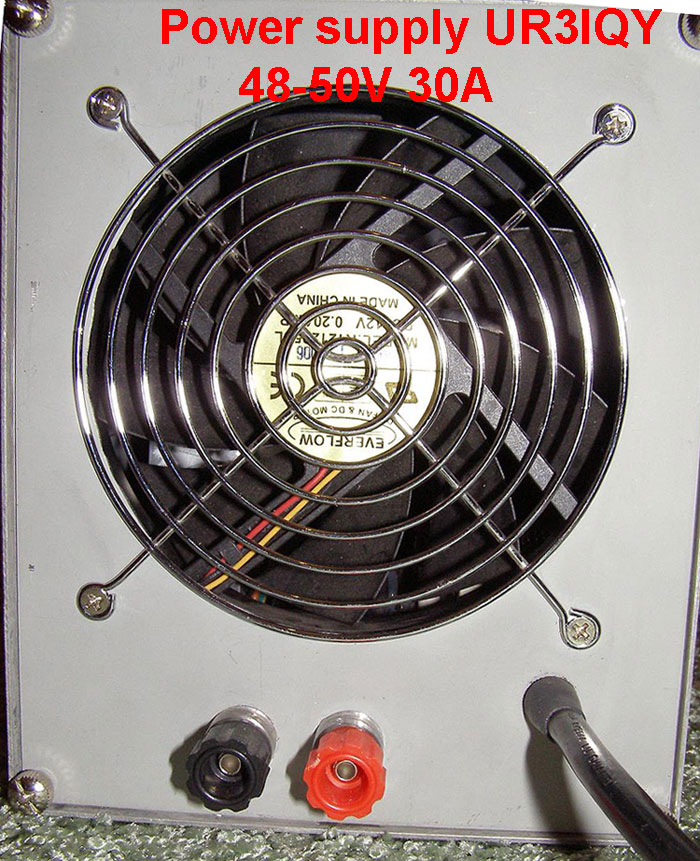
Second variant remake of power supply SE-1000:
This method was suggested by Alexey UR3IQY. Big current can be taken off from SE-1000. For this purpose diode bridge should be replaced with more powerful and placed on another heat sink. Power supply can be completely disassembled. Place the heat sink with bridge at biger area. Heat sink - made from the profile of width 122mm. For cooling - you can use computer fan - size 120x25mm.
Such kind of fan, like this - provides enough airflow with the minimum of noise. Photo is here >>>>>>
As a variant �classic� power supply was considered.
I.e. powerful transformer 220V/47V + rectifier on Shottky diodes + electrolytic capacitor with big capacity in filter. �Laboratory work� was carried out on theme which scheme of rectifier is the most optimal for such of power supply. As a result of such work we can see that the most preferred is the bridge circuit loaded on electrolytic filter capacitor not less than 30000mF. I didn't find Shottky diodes of current 50A in suitable constructive execution and in acceptable price so usual rectifiers KBPS5002 were tested. The bottom of the amplifier body servers as heat-sink for rectifiers. Electrolytic capacitor 47000mF?63V was applied in the filter. Also board where 8pcs of capacitors 10000mFx63V was developed.
So we have total capacity of 80000mF?63V that can be used if we want to make more powerful amplifier. For example to add power of two 500-600W amplifiers. Protection of rectifier diode has to be foreseen for charging of such a big capacity. Big charging current is arises in the moment of switching. The scheme of �gradual start" ("soft start") was developed for decrease initial charging rate. In the moment of switching - voltage of 220V comes to the primary of transformer through powerful resistor that limits starting current. After time - this resistor will be closed, by the relay contacts and the power supply is ready to work.
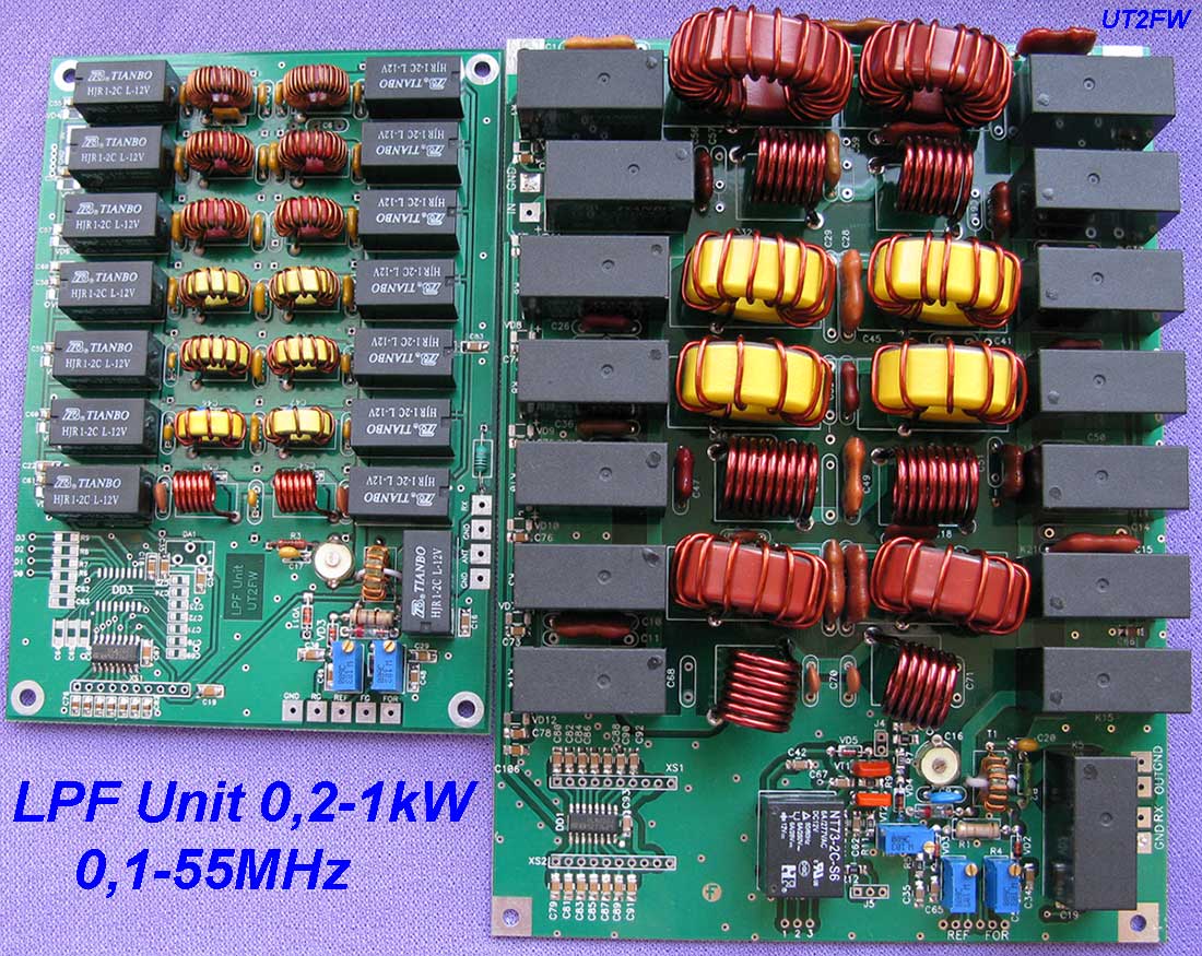
A little information about the LPF board.
Relay is the most reliable element of LPF Unit. Therefore choosing of the relay is a very carefully task. I had to look over more than ten different types and as a result stopped on TRA2 L-12VDC (16A 240VAC) relay.
Relay producer http://www.tianbo-relay.com promises presence of silver on contacts and maximum current up to 20A. It is important that the relay construction is such where contacts remote from the electromagnet. Between opened relay contacts up to 1000VAC and between the coil and the contacts up to 5000VAC.
There are 7 filters in LPF Unit and such distribution range160m, 80m, 40m, 10-20m, 17-15m, 12-10m, 6m. There are two variants of filter controlling:
1. Low potential, i.e. GND abridging by passing a transistor or the switching contact.
2. By the positive voltage supplying of 2,5-5V. DD1 ULN2003 is used for this purpose.
So LPF Unit can be controlled by as electronic method by the signals from the transceiver or SDR as by the usual switch.
SWR-meter was set on LPF unit. SWR-meter scheme is standard with ferrite ring. There are 4 signals have been taken out from the SWR-meter scheme. FOR-REF signals can be given on LED through the additional limiting resistors. For example red LED will show FER and the green FOR. FOR Gain\REF Gain signals are used for the pointer device SWR-meter.
Additionally I introduced a scheme that switches from the increased REF let's me call it as �protection�. REF voltage from the SWR-meter enters on the scheme with �latch�. Additional relay is managed by this scheme and it turns on at increased REF. Amplifier can control the relay contacts. For example additional ATT can be turned on at the entrance of the amplifier. So it can make work more saved at the increased REF values. For displaying the �protection� turning on there is voltage at the external LED that will glow when �protection� will be turned on. To return �protection� to the initial state press the reset button J4 or remove supplied voltage from the board.
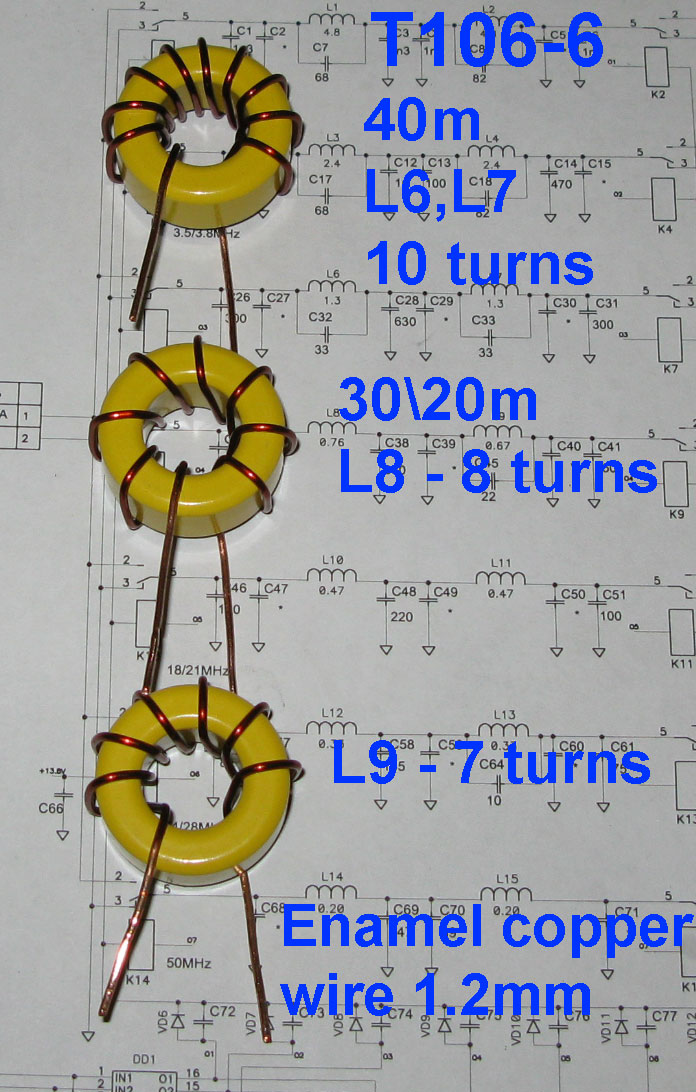
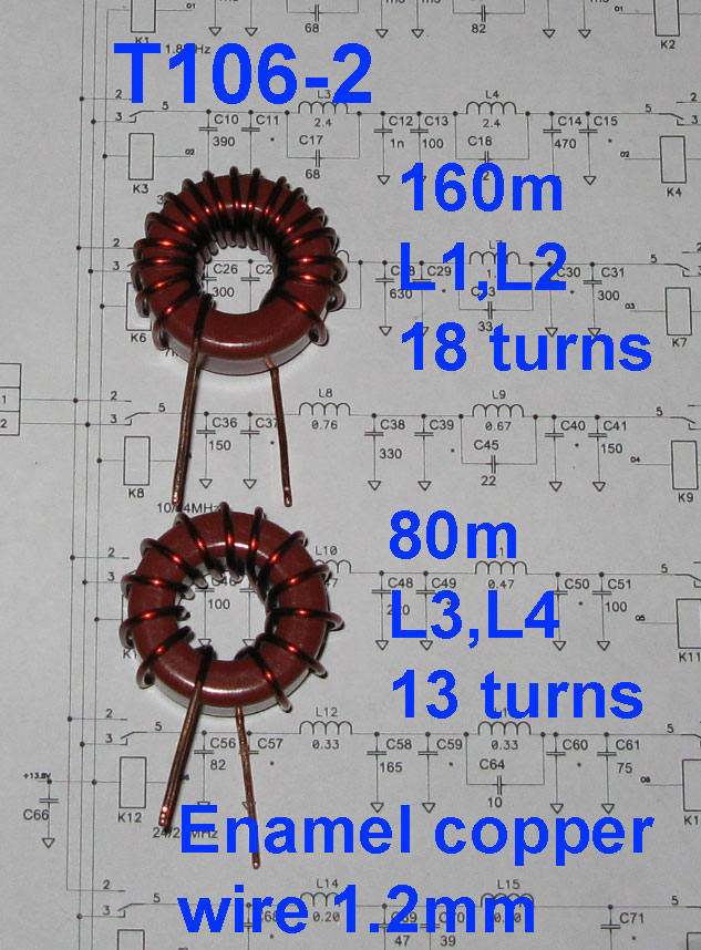
Applied LPF filters are of the fifths order. This is the most popular filters applied in the amplifiers of such class. Ring cores of http://www.micrometals.com - T106-2, T106-6 were used for decreasing of gabarits. Coils without carcasses are used for the ranges 18-50 MHz. Program RFSim99 was used for the filters data calculation. At the pictures you can see the characteristics of each LPF in two variants, red color is a linear scale and blue color is logarithmic scale. 50 MHz range for LPF used as additional.
SWR-meter scheme - has own peculiarity. I apply two LEDs in the antenna tuners additionally to the pointer instrument. A green LED for (XP3) and a red REF (XP1). This is very visually, because it is easy to control antenna matching condition by the brightness of the LEDs glowing. For a red LED glowing even on a small values of REF voltage doubling was leaded (VD1). Germanium diode can be used for getting bigger voltage of VD1. Then a red LED will start to glow even on a very small REF values. If you don't need it then all three diodes in the SWR-meter can be silicon (VD1,VD2,VD3). It's desirable - use the LEDs with the minimum current glowing.
The coils data:
160m � T106-2, L1,L2 � 18 turns
80m � T106-2, L3,L4 � 13 turns
40m � T106-6, L6,L7 � 10 turns
30/20m � T106-6, L8 � 8 turs, L9 � 7 turns
Red toroid cores T106-2
Yellow toroid cores T106-6
Enameld copper wire, diameter 1.2 mm
18/15m � 8 turns
12/10m � 7 turns
6m � 6 turns
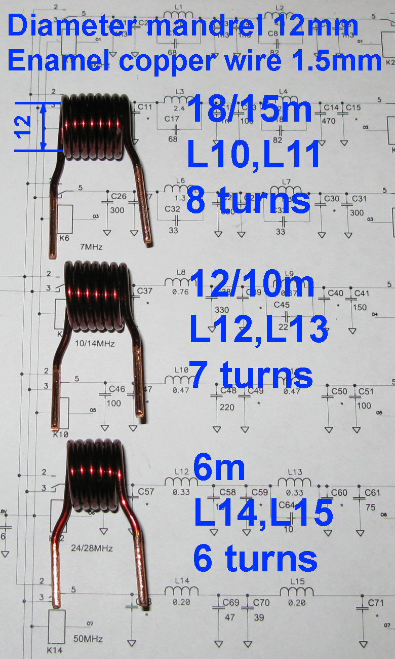
Diameter mandrel 12mm,
Enamel copper wire, diameter 1.5 mm
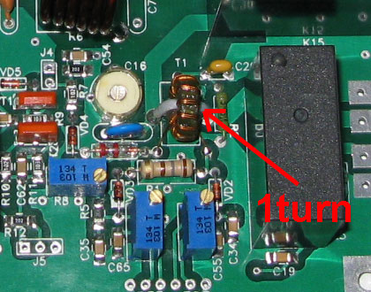
SWR transformer coil:
T1 = 15 turns in two wires
FT-37-43 toroid core (color black)
Enameled copper wire, diameter 0.3 mm
Add one turn of tinned copper through the core when installing the SWR coil on the board. See pictures.
![]()

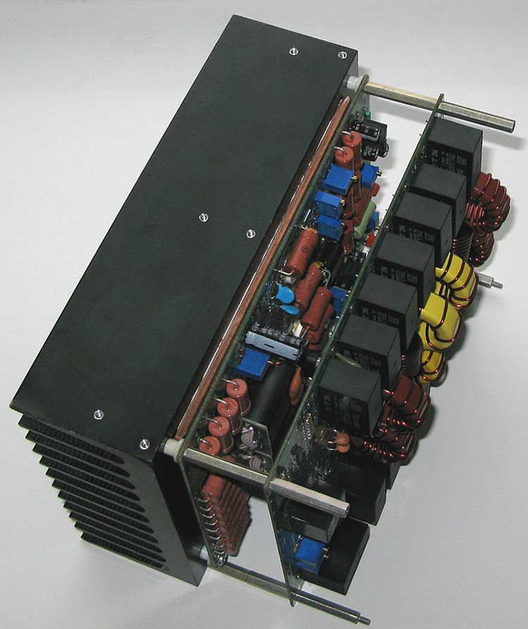
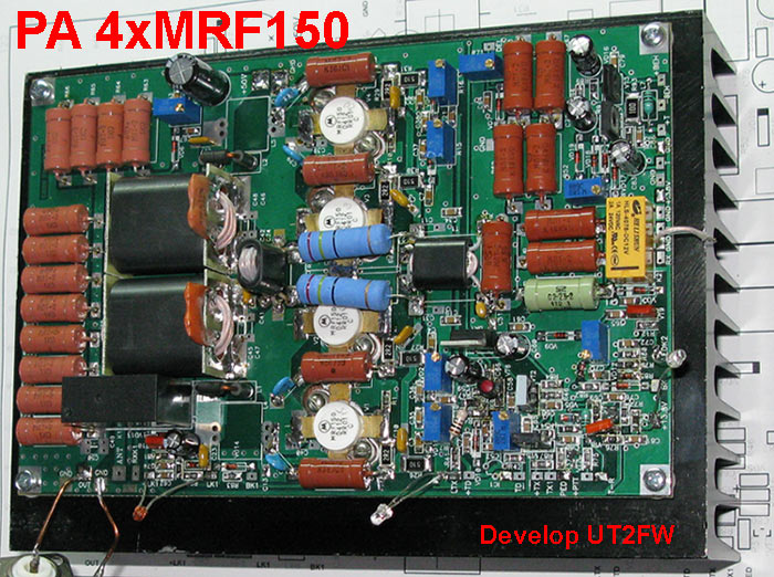
The amplifier is built on 4 x MRF150 transistors. It's so popular solution for the amplifier of power up to 600W. S?heme of this amplifier - is used by Communications Concepts, Inc., Ameritron, Tokyo Hy-Power and a lot of other companies. The most popular among the radio-amateurs - is kit EB104, from Communications Concepts, Inc. Also we have a lot of detailed descriptions of the amplifiers with 4?MRF150 in the Internet. So I describe only schemes being added by myself.
The main task - is build stability and reliability of the amplifier.
Input attenuator is executed on the resistors R36,48,51-53,67-69. Voltage that controls scheme VT1,8,9 is taken from the diode VD9. This scheme is similar to the �protection� scheme of the board LPF. R72 regulates scheme sensitivity. When input voltage of amplifier exceeds, given start to threshold control of the transistor VT1. Then relay K1,2 will turn to RX mode.
Scheme with the �clip�. This scheme will be working when:
1. Turn "ON" the amplifier and wait, until the capacitors discharge
2. Loop Reset � XP4 on the frame.
Output of amplifier is loaded on resistors R55-66. I call it - �protection from stupid�. Total resistance is 510 Ohm. Assume that amplifier has no load for example relay K1 is out of order or antenna wire is break. In this case from SWR=10 the amplifier will be loaded on these resistors. The voltage on VD6 - increased and will open VT2 transistor. Bias voltage decreases for VT1-4 and �protection scheme� VT1,8 will be activated. It's will turn relay K1,2 "ON" - to the RX mode.
Relay K1 commutes output of the amplifier. There are two variants of usage.
With K1 relay set up on board, or without it. Sometimes very simple input filters are used in the receivers. LPF filters of the amplifier can be used as the additional improved of the receiver selectivity. So K1 was introduced into the scheme. If this relay is set up then the receiver input will be connected with the antenna through the LPF filters. The "XP15","XP16" - is not used here. And "J3" "OUT PA" on the LPF board connect with the "ANT". If you don't need such regime don't set up K1 on the board. The "XP15" - RX connect by the slim coaxial cable with contact "J2 RX" on the LPF board. And "XP16" "OUT" - is connect with J3 OUT PA contact on the LPF board.
Possibly you live in Italy and don't like to use LPF filters. Such amplifiers are made by popular Italian brand RM www.rmitaly.com. Powerful amplifiers KL500 and KL800 (power up to 600W PEP) of this brand haven�t any filters. This amplifier for 4xMRF150 can be used in the analog variant. For this purpose relay K1 should be set up and contacts XP15,16 are not used. Connect antenna to the "XP14" - "ANT".
"XP1","XP2"; "XP11","XP12"; "XP17","XP18" - this contacts is intended for LEDs. These LEDs is show relay K1, K2 regime and presence of bias voltage for V1-4 transistors. The loop VD7-R71-XP6 introduced for the external microprocessor. It is possible to make a control of the amplifier from the microprocessor. For this purpose control signal from VD7 diode is needed.
The scheme on IC1 - this is intended for super heat protection of amplifier. When temperature is to rising - the voltage on resistor R43 also rising. This voltage will be opening IC1 that shunts bias circuit of V1-4 transistors. Bias decreasing thereby standing current of V1-4 transistors is also decreasing. LED connected to the contacts XP11,XP12 indicates presence of bias voltage. Thermistor, that is fixed to the heat sink - is connect to the contacts XP9,XP10.
Transistors VT7, VT5 form +TX voltage and control of RX-TX mode. You can switch the amplifier to TX mode in two ways. First method - is by pedal, that can be connected to XP22 PED contact. Second method - is to supply voltage of +5 � 15 V to XP23 +TX_IN contact.
A nominal thermal condition of the amplifier with a minimum noise from the fan - is a very difficult task. Because the amplifier can be used as in partial load mode working with DX as in a very hard conditions when working in TEST mode.
So supplying of fixed voltage to the fan will not be optimal. This is desirable, that in the partial load mode of the amplifier work reduced supply voltage should be given. Thereby minimum noise from the fan, can be obtained. The maximum cooling is need at the TEST MODE. In this variant - fan is used id maximum productivity.
Therefore maximum voltage for the fan, should be supplied.
Scheme of the fan control - was made on transistors VT3, VT4. Thermistor that has thermal contact with the heat sink - connects to the contacts XP26,XP27. Transistor VT4- will be opens, when the temperature of the heat sink will rises.
Corresponding output voltage on the contacts XP28 "+FAN TURNS", XP29 "�FAN TURNS" increases. Resistor R90 regulates voltage limits on the ventilator in dependence on temperature.
Fan turns changing smoothly in dependence on temperature. R93 resistor limits the maximum voltage on the fan. When turning to TX mode - VT3 transistor is turning on and combined stress goes on the fan. Corresponding in TX mode - fan is turning on full turns. For this PA - has been used two cooling fans. The fans is turned on simultaneously. Two ventilators with size 120x120mm were used for the computer equipment.
Why two fans, but not one? In my opinion it is better to apply two fans for supplying necessary air flow on minimum noise. One fan (inside body) blows the heat sink and the power unit. Second fan - blows out air from the body. Working of two fans on reduced turns will be quiet. Instead of one fan for supplying similar air flow. Today choice of 120x120mm fans is huge � China producer is not sleeping but working hard!!!
Have to be attention, when choosing the fan! His productivity and noise characteristics. Usually more productivity - more noise. So you need to choose type of fans for the given task. You can find it in the Internet reviews - with different fans characteristics. For a short-term amplifier (DX) working - is reasonable to choose models with a small quantity of turns and low noise.
For working in TEST modes with maximum productivity - also can be chosen. I will specify some models of the fans, that shows better results in it's category. Fans for TEST: : Thermalright TR-FDB-12-2000 (2000 rpm), Scythe Slip Stream (1900 rpm), Scythe S-FLEX SA1225FDB12H (1900 rpm), Scythe Gentle Typhoon120 D1225C12B5AP-15 (1850 rpm), Noiseblocker MF12-S3HS (1800 rpm).
Fans for DX: Noiseblocker MF12-S1 (750 rpm), Noiseblocker FLX (1200 rpm), Noiseblocker MF12-S2 (1250 rpm), Thermalright TR-FDB-12-1300 (1300 rpm), Zalman ZM-F3 (1800 rpm).
Do not follow the information given by a producer on his fan models. List of the fans always fills up with new models - so make a choice and follow the last comparative reviews.
The rest part of scheme is standard for such amplifier. Rest currents of the transistors V1-4 regulates by the resistors R7,8,15,16 of 150mA on transistor. Transformers T1, T4-5 has transformation ratio 1:9. Windings 1-2 T1 and 3-4 T4-5 have on three winds of stranded wire in heat-resistant isolation. For the transformer T2 was used the same core as for T1. Winding 1-2 has one wind, windings 3-4, 5-6 on tree winds. All windings are made by the wire of maximum possible section. Suitable transformers presented on the web sites http://www.rfpowersystems.com www.communications-concepts.com
For the throttles L1,2 ferrite beads are used. It should be dresses on the wire with diameter not less than 1,2mm for obtaining minimum inductance in 2.0uH. Capacitors ?51,32,33,45-48 supply necessary correction of frequency characteristics of the amplifier.
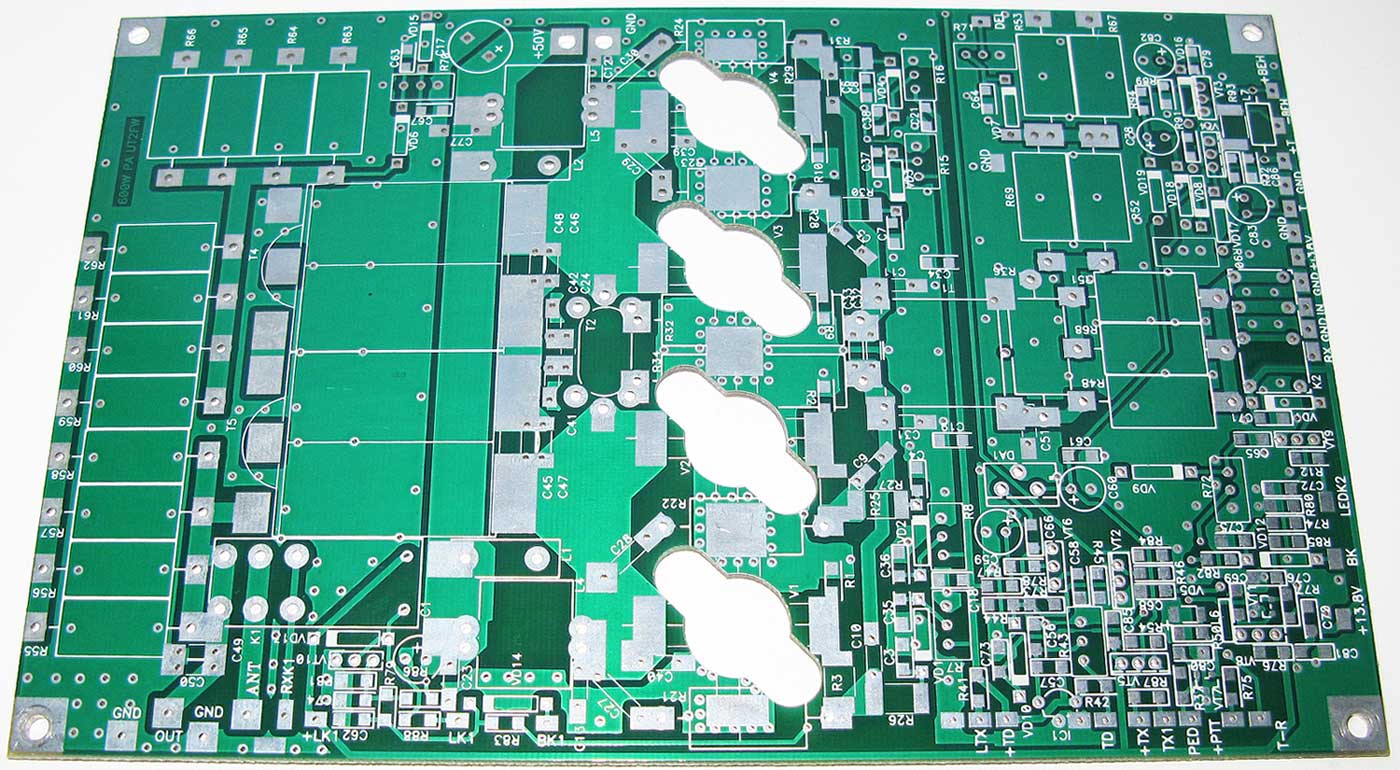
All elements that should be on board are shown on the scheme.
PCB produced with the possibility of applying different scheme solutions. Which scheme solution to apply decides constructor. It will depend on his interests and facilities. For example instead of transformer T2 two throttles L4,5 can be used. Rings FT82-43 were used for the cores of that throttles. Winding includes 7 windings in two wires with the diameter 1,0mm. This variant can be more preferable because the transformer T2 getting warm very quickly. Amplitude � frequency characteristic of the amplifier can be corrected with the help of resistors R21-24.
Elements VD7,12,14; R79,83; L6 are for possible control from the microprocessor.
Link to YouTube videos: http://www.youtube.com/user/UT2FW