Antenna Analyser 1.8-30 MHz (PIC16F819+AD9835)
Introduction.
Some years ago were developed the schemes and were tested in work the synthesizers with DDS chips. So, I've got an idea to use such synthesizer in device for the antenna tuning as internal generator.
To do one's best Vladimir RX6LDQ and me have made such device.
Main task during the development was the minimal cost of such device, because similar products of well-known producers by their cost are comparable with good antenna and we don't want cough up the money on such "toy". Especially because of its rare necessity - usually we build antennas not more than 1 time per year or even per few years.
Almost 3 hundred bucks (or even more) pay for such device, use it 1 - 2 times and then forget about it. Who wants this? So, pay for such device a lot of money is not efficiently. Although it's sufficiently profitably because tuned with the help of Antenna Analyser antenna wins during the work on the direct "on-air" transmission.
During the execution of prior laboratory works were tested few variants of measuring devices; thankfully this theme doesn't need any developing because there are a lot of manuals of different schemes, starting with complete classical and ending with the simplest measuring devices on one diode.
I could stop at the simplest variant such as it made in the antenna analyser MFJ-249. What do we need? - generator, frequency meter and measurer SWR. I have decided to do maximum complex variant, which cost will be not more than 100 USD.
So, what is it?
I'll try to tell you briefly and understandable.
Chip of the direct synthesis such as DDS AD9835 (Analog Devices) is using as generator. Its output signal is filtered by filter with 35Mhz cutoff frequency. Then the signal is amplifying by the powerful wide-band transistor amplifier. Amplitude of the signal can reach up to 2V. Usual value at the measuring device is near 1,5V. With the high generator amplitude when the powerful noises in SW range are present there will not be big problems with tuning.
Signal from generator goes to a measurer - detector type and working principle of which is on the web-site http://users.on.net/~endsodds/analsr.htm - author is Jim Tregellas VK5JST. We have 3 signals from the measuring device:
1. Amplifier voltage, 2. Voltage drop on the reference resistor, 3. Voltage at the load
These signals are amplified by six operational amplifiers and supplies to the ADC inputs of the PIC16F819 microcontroller. There is a program in the microcontroller that performs all mathematic calculations and the end results we see as understandable digits at the LCD as two lines. Traditionally all mathematics and programming belongs to Vladimir RX6LDQ.
What functions are there and how to use it?
Depending on the type of DDS that is used output cutoff frequency of generator can be up to 300 MHz. But because the price supposed to be possibly minimal the decision has been made to take cutoff frequency as 30 MHz.
Device control is carrying out with the help of four buttons - two buttons are 'Frequency transferring' up - down by frequency, third button is 'Menu', and fourth button is 'Step rearrangement' by frequency. Step rearrangement can be 1kHz, 10kHz, 100kHz, 1MHz.
Measurements can be executed in lines with wave impedance such as 50Ohm, 75Ohm, 300Ohm, and 600Ohm.
Initially the device is turned on to perform measurements in 50 Ohm lines. Error of the device is increasing when the measurable resistance is deviating from the resistance on which the device is graduated. Practical data: if the device is graduate up to 50 Ohm then during changing an active resistances up to 200 Ohm error will be not more than 2%, up to 500 Ohm near 5%, higher than 500 Ohm it sharply increases and can be more than 10%. Then the device measures almost up to 1kOhm with an error up to 15-20 %.
Antenna Analysers are used for the measurements in lines which are tuned on a wave resistance of them rather than universal devices for the measurement of R,C,L,Z and X. Therefore we moved away the theme of "UNIVERSALITY" of this device and concentrate our attention on a minimal cost. If the cost of analyser is comparable with the cost of good antenna then why do we need Antenna Analyser? Buy ready antenna and use it without wasting of money to the additional devices!
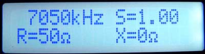
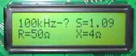
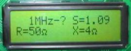
Information at the antenna analyzer display appears in such way: upper string is Working frequency in KHz, S-SWR and lower string is R-active resistance and X- reactance.
To determine a sign of the reactance push the button of frequency transferring - during the increasing of frequency, capacitive component will decrease inductive component will increase. During the decreasing of frequency - vice versa. During the frequency transferring all parameters of the measurement process are saving. For example we are interested in the frequency of a minimal SWR - push 'frequency transferring' button and look to the values of S. Or we should find on what frequency the resistance of our antenna closely related to 50 Ohm - push 'frequency transferring' button and look to the values of R. I.e. control of the device is very simplified.
Device supplying is from any source by voltage 12-20 V and by current 250 mA. It has two internal potentiostats on 5V and 10V so even non stabilized voltage can be supplied. The more voltage will be the more power will spread at the stabilizers, correspondingly they will getting warmer. Especially in case of LCD application with light. The device consumes not more than 150 mA starting from 12 V of a supplier during the usage of LCD without light. If we will use LCD with light then consumption increases (depending on current consumption by the light) up to 200-250mA.
Before using the device requires a calibration. Push the button "Menu" and will see at the display -
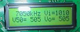
Upper string: Working frequency in KHz, Vi - input level at the measurer (voltage of generator).
Lower string: V50 - voltage drop at the reference resistor, Vo - voltage on a load.
Fix the frequency on which the antenna should work. When analyzer is turning on initial frequency at the display is 7050 kHz. If we need to switch far away from this frequency to avoid a long waiting of the 'frequency transferring' button make the most rough step in 1 MHz and quickly reconstruct as near as you can to the required frequency by the transferring buttons. Adjust more accurately during choosing the less step of reconstruction.
How to choose step? Push the button 'Step selection' and by transferring buttons of frequency choose the necessary step and then push the 'Step selection' button and selected step has been saved.
Then setup the levels at the measurer on the selected frequency. By resistors calibrators setup the level Vi=1021-1022. Attention! Limiting voltage value that is measured by an internal ADC of microprocessor can be 1022 (numbers 1022 displayed at the LCD are not a voltage! It is relative value). So if to supply on it's input voltage of high level anyway the display will show 1022 value. Therefore by a calibration resistor should be given such level in which voltage at the input of ADC will be near the breaking point but not exceed it. I.e. numbers at the display can change from 1022 to 1021.
Then connect to antenna connector calibrating resistance of the required nominal. During the calibrating resistance attaching the value of Vi will be decreased. And it will be decreased depending on the nominal of the calibrating resistor. For example (look to the upper photo "Menu" at the display) it have been decreased up to value Vi=1010 during the resistor on 50 Ohm is attaching. By the calibrating resistors setup a half - voltage from Vi value in the windows V50 and Vo. I.e. 1010/2=505. Setup by the calibrating resistors V50=505 and Vо=505 and that's it! Device calibration is done. Push the button "Menu" to exit to changing mode.
Disconnect the calibrating resistance, connect our antenna and look at the display to its parameters. It is something like "theoretical and mathematical" ways of the calibration that are not consider spread of factors and diode quality in the measuring detector, temperature influence and amplitude-frequency characteristics of the synthesizer amplifier.
Which calibration dictates the practice to us - look at the User Manual.
Practical realization.
Analyzer board has been made on the high-quality double-sided fiber-glass plastic with the metallized holes. Maximum of foil is left from both sides. Chips appear just from the one side of a board because they can't be soldered mirror-like and the remaining details can be soldered from the any side of a board. This information is for those who risk to replicate the device and want to minimize the thickness of the completed board. Elements on the board are usual not SMD. Just DDS AD9835 SMD synthesizer because the company does not produce it in another variants. You can use any of two-lines LCD, no limits here.
LCD with light will be good but without too - for brightness setting there are additional elements on the board. It is necessary to take into account that fact that light consumes current from a power supply pretty well. It's necessary to provide an additional tumbler with forced light deactivating if you suppose to use analyzer with battery supply. There is such LCD of Chinese production that has non regulating light and it actuates at the same time with energization.
Depending on the type of LCD resistors nominal R21, R22 are fitting with с HY-1602В3 R21=12k, R22=1k. I.e. fit by required contrast LCD resistor R22. Germanium and high quality diodes VD3-VD8 should be of the same type.
Filter elements C9,C8,C10,C11,C32 and coils L1,L2 determines amplitude-frequency characteristics and filtrates the harmonics which are more than 35 MHz. Coils: take arbor 4mm in diameter and reel on it 22 curls by a wire with the diameter approximately 0,4mm. Solder the coils at the distance of 3-4mm from a board. Then whelm them with the paraffin (stearin, wax) to fix them in a future work with the device. Attention! Don't whelm the coils with glue!
R1X-R2X are multiturn resistors - look at the board photo. With this type of resistors it is enough one resistor on 10-20kOhm instead of two with in series larger and lower nominal. There are two resistors connected in series on the board. By one resistor (10k) will tune roughly by another (1k) - accurately.
Supervisor МС33064Р-5 can be not soldered because all works without it and it serves as protector from the errors in supplying voltage. Transformer T1 is ferrite ring 7mm in diameter and permeability 1000-2000. There are 8 curls at 2 wires on the ring. Wire is 0,24-0,31mm in diameter.