Antenna impedance may be either resistive or complex (that is, containing resistance and reactance). This will depend on whether or not the antenna is resonant at the operating frequency. You need to know the impedance in order to match the feeder to the feedpoint. Some operators mistakenly believe that a mismatch, however small, is a serious matter. This is not true. The importance of a matched line is described in detail in the Transmission Lines chapter of this book. The significance of a perfect match becomes more pronounced only at VHF and higher, where feed-line losses are a major factor.
Some antennas possess a theoretical input impedance at the feedpoint close to that of certain transmission lines. For example, a 0.5-l (or half-wave) center-fed dipole, placed at a correct height above ground, will have a feedpoint impedance of approximately 75 W. In such a case it is practical to use a 75-ohm coaxial or balanced line to feed the antenna. But few amateur half-wave dipoles actually exhibit a 75-ohm impedance. This is because at the lower end of the high-frequency spectrum the typical height above ground is rarely more than 1/4 l. The 75-ohm feed-point impedance is most likely to be realized in a practical installation when the horizontal dipole is approximately 1/2, 3/4 or 1 wavelength above ground. Coax cable having a 50-ohm characteristic impedance is the most common transmission line used in amateur work.
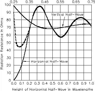
Fig 20.1 shows the difference between the effects of perfect ground and typical earth at low antenna heights. The effect of height on the radiation resistance of a horizontal half-wave antenna is not drastic so long as the height of the antenna is greater than 0.2 l. Below this height, while decreasing rapidly to zero over perfectly conducting ground, the resistance decreases less rapidly with height over actual ground. At lower heights the resistance stops decreasing at around 0.15 l, and thereafter increases as height decreases further. The reason for the increasing resistance is that more and more of the induction field of the antenna is absorbed by the earth as the height drops below 1/4 l.
Fig 20.1—Curves showing the radiation resistance of vertical and horizontal half-wavelength dipoles at various heights above ground. The broken-line portion of the curve for a horizontal dipole shows the resistance over "average" real earth, the solid line for perfectly conducting ground.