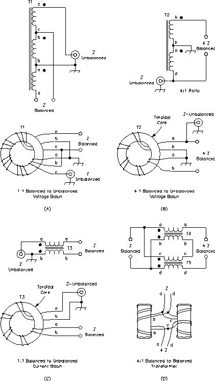
At HF and even at VHF, broadband baluns are generally used nowadays. These can be divided into two distinct categories: voltage baluns and choke (or current) baluns. Examples of the two types of baluns are shown in Fig 19.13.
The voltage baluns of Fig 19.13A and Fig 19.13B cause equal and opposite voltages to appear at the two output terminals, relative to the voltage at the “cold” (coax cable ground) side of the input. If the two antenna halves are perfectly balanced in impedance with respect to ground, the balun will force the voltages to be equal, and the currents flowing from the balun’s output terminals will be equal and opposite. No antenna current will flow on the feed line, and the feed line will not radiate. If the load is balanced, the 1:1 voltage balun of Fig 19.13A performs exactly the same function as the current balun of Fig 19.13C, as there is no net current in winding b. If the antenna isn’t perfectly symmetrical, however, unequal currents will appear at the balun output, despite equal voltages, causing antenna current to flow on the line, an undesirable condition leading to line radiation.
Another potential shortcoming of the 1:1 voltage balun is that the windings
appear across the line. If the windings have insufficient inductive reactance (a
common problem, particularly near the lower-frequency end of its range), the
system SWR will be degraded. The choke, or current balun, is generally
recommended for use at the junction of the antenna and feed line. However,
voltage baluns are still commonly used in this application and serve a useful
function if the user is aware of their shortcomings.
While voltage baluns cause equal and opposite voltages to appear at their
outputs, choke or current baluns force equal and opposite currents to flow. The
result is that currents radiated back onto the transmission line by the antenna
are effectively reduced, or “choked off,” even if the antenna is not
perfectly balanced. If winding inductive reactance becomes marginal at lower
frequencies, the balun’s ability to eliminate antenna currents is reduced, but
(for the 1:1 balun) no winding impedance appears across the line.
For either type of balun, if induced current on the line is a problem, perhaps because the feed line must be run in parallel with the antenna for some portion of its length, additional baluns can be placed at approximately 1/4-l intervals along the line. Current baluns are particularly useful for feeding asymmetrical antennas with balanced line.

Either type of broadband balun can be constructed using a variety of techniques. Construction of choke (current) baluns is described here. The objective is to obtain a high impedance for currents that tend to flow on the line. Values from a few hundred to over a thousand ohms of inductive reactance are readily achieved. These baluns work best with antennas having resonant feed-point impedances less than 100 W or so (400 W for 4:1 baluns). This is because the winding inductive reactance must be high relative to the antenna impedance for effective operation. A rule of thumb is that the inductive reactance should be four times higher than the antenna impedance. High impedances are difficult to achieve over a wide frequency range. Any sort of transformer which is operated at impedances for which it was not designed can fail, sometimes spectacularly.
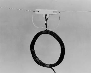
The simplest construction method for a 1:1 balun for coaxial line is simply to wind a portion of the line into a coil. See Fig 19.14. This type of choke balun is simple, cheap and effective. Currents on the outside of the line encounter the coil’s impedance, while currents on the inside are unaffected. A flat coil (like a coil of rope) shows a broad resonance that easily covers three bands, making it reasonably effective over the entire HF range. If particular problems are encountered on a single band, a coil that is resonant at that band may be added. The coils shown in Table 19.4 were constructed to have a high impedance at the indicated frequencies, as measured with an impedance meter. Many other geometries can also be effective. This construction technique is not effective with open-wire or twin-lead line because of coupling between adjacent turns. An air-core 4:1 choke balun is shown in Fig 19.15.

Fig 19.14 — RF choke formed by coiling the feed line at the point of connection to the antenna. The inductance of the choke isolates the antenna from the remainder of the feed line.

Fig 19.15 — 4:1 air-core current balun. This balun is rarely encountered nowadays, having been supplanted at HF by more compact broadband balun transformers wound on toroidal cores.
Ferrite-core baluns can provide a high impedance over the entire HF range. They may be wound either with two conductors in bifilar fashion, or with a single coaxial cable. Rod or toroidal cores may be used. Current through a choke balun winding is the “antenna current” on the line; if the balun is effective, this current is small. Baluns used for high-power operation should be tested by checking for temperature rise before use. If the core overheats, add turns or use a larger or lower-loss core. It also would be wise to investigate the imbalance causing such high line antenna currents.
Type 72, 73 or 77 ferrite gives the greatest impedance over the HF range. Type 43 ferrite has lower loss, but somewhat less impedance. Core saturation is not a problem with these ferrites at HF; since they overheat due to loss at flux levels well below saturation. The loss occurs because there is insufficient inductive reactance at lower frequencies. Eight to ten turns on a toroidal core or 10 to 15 turns on a rod are typical for the HF range. Winding impedance increases approximately as the square of the number of turns.
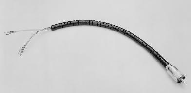
Another type of choke balun that is very effective was originated by M. Walter Maxwell, W2DU. A number of ferrite toroids are strung, like beads on a string, directly onto the coax where it is connected to the antenna. The “bead” balun in Fig 19.16 consists of 50 FB73-2401 ferrite beads slipped over a 1-ft length of RG-303 coax. The beads fit nicely over the insulating jacket of the coax and occupy a total length of 9-1/2 inches. Twelve FB-77-1024 or equivalent beads will come close to doing the same job using RG-8A or RG-213 coax. Type-73 material is recommended for 1.8 to 30 MHz use, but type-77 material may be substituted; use type-43 material for 30 to 250 MHz.

Fig 19.16 — W2DU bead balun consisting of 50 FB-73-2401 ferrite beads over a length of RG-303 coax. See text for details.
The cores present a high impedance to any RF current that would otherwise flow on the outside of the shield. The total impedance is in approximate proportion to the stacked length of the cores. The impedance stays fairly constant over a wide range of frequencies. Again, 70-series ferrites are a good choice for the HF range; use type-43 if heating is a problem. Type-43 or -61 is the best choice for the VHF range. Cores of various materials can be used in combination, permitting construction of baluns effective over a very wide frequency range, such as from 2 to 250 MHz.
Table 19.4 — Effective Choke (Current Baluns)
Wind the indicated length of coaxial feed line into a coil (like a coil of rope)
and secure with electrical tape. The balun is most effective when the coil is
near the antenna. Lengths are not critical.
Single Band (Very Effective)
| MHz | RG-213, RG-8 | RG-58 |
| 3.5 | 22 ft, 8 turns | 20 ft, 6-8 turns |
| 7 | 22 ft, 10 turns | 15 ft, 6 turns |
| 10 | 12 ft, 10 turns | 10 ft, 7 turns |
| 14 | 10 ft, 4 turns | 8 ft, 8 turns |
| 21 | 8 ft, 6-8 turns | 6 ft, 8 turns |
| 28 | 6 ft, 6-8 turns | 4 ft, 6-8 turns |
Multiple Band
| MHz Freq | RG-8, 58, 59, 8X, 213 |
| 3.5-30 | 10 ft, 7 turns |
| 3.5-10 | 18 ft, 9-10 turns |
| 14-30 | 8 ft, 6-7 turns |