APRS is a new "game" for radio amateurs. Apart from the known D-7, D-700 Kenwood where
they cover this mode without external
modem, the Tiny Trak is a second simple choice
for tracking, simply by using a usual VHF and TinyTrak as APRS modem.
However, they need a GPS in order to be able to work as mobile.
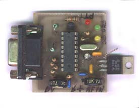
This page describes the connection of my homebrew
Tiny Track with Etrex
Garmin (Fig.1).
Etrex is a cheap model of Garmin.
You can find it in offers between 50 - 80 $ and it is ideal, at my opinion,
for this kind of application . This is the "good news"!
Fig.1
The "bad-news": Unfortunately, the eTrex's output data-cable which is necessary between GPS and Tiny does not exist in offer and it is very expensive, roughly 40- 50$!
Fortunately is a simple cable and we can easily make it, as "homebrewers" !
 |
 |
| FIG.2 |
FIG.3 |
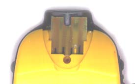
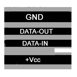
Fig.2 above shows the connection-place into Etrex which took place in the Upper Back-side of GPS body. It has 4 contacts: GND, Data-out, Data-In & +Vcc.
Fig.3 shows my Homebrew TinyTrak. It is a very small PCB with a female DB9 connector for the connection with a GPS or PC.
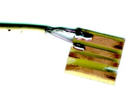
Fig.4 below shows my homebrew-Plug for Etrex Gps. The smal piece of PCB has four copper strips.
This printed-board is made from thin PCB, about 0.5 mm thickness.
If the PCB is thicker than 0.5mm, then will not enter in the 2 side-slots of GPS. In this case by using a small rasp, simply
"eat" the 2 edges on both sides of pcb, in order to has a thickness of about 0.5 mm.
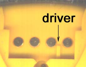
Another point: Etrex has between +Vcc & Data-in contactors a "driver", into the plastic case (see Fig.5).
 |
 |
| FIG.4 |
FIG.5 |
Thus, it's necessary to make a "slot" into PCB with similar dimension, in order to enter the driver, ensuring the right admission of PCB.
I've used a piece of RG174-cable between PCB and TinyTrak. The shield connected to GND and the
centre cable to Data-Out. I've not used the other 2 connections (Data-In & Vcc).
Fig.6 below shows
the PCB-plug into GPS connection -place.
 |
 |
| FIG.6 |
FIG.7 |
Fig.7 shows the PCB -piece with tracks. It's exactly 17mm wide.
Now, we suppose that you have made the PCB-plug and stuck also a male DB9 in the other
end of cable, to the TinyTrak. Keep in mind, GND must be connected to Pin 5 and Data-Out to Pin 3 of
DB9.That's all - we finished?
Nooooo !
Now it will be supposed we certify that the GPS is rightly configured in order to give NMEA protocol in the Data-output.
| 1) Turn on the GPS. Go to "Menu" and choose "Setup"( by HighLigthing that, see Fig.8) |
| 2) On "Setup" set "INTERFACE" (Fig.9) |
| 3) On "Interface" set "NMEA OUT", 4800 Baud (Fig.10) |
Now, you are OK 100%. After that, connect the GPS with Tiny-Trak and go Outside... "turn-on" the GPS. After few seconds or few minutes, you must have "Full scale" on bar-signal Satellite reception . Then, the GREEN Led
on TinyTrak "lights", confirming the "Data-reception". It Works !
That's all folks ! Have Fun !