6
Elements
VHF Yagi
antenna

FIG.1 shows a 6 elements VHF Yagi "homebrew" antenna
designed
with YAGIMAX 3 and made by SV1XY and me with excellent
results
on local and satellites contacts.(UO-14, AO-27 etc.)
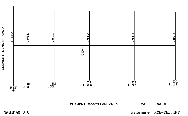 |
FIG.2 shows a graph for the SWR, GAIN and F/B ratio.
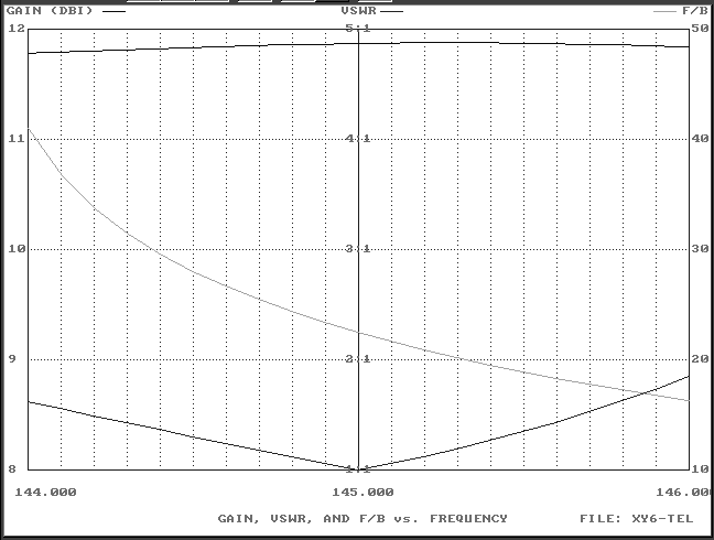 |
FIG. 2
The maximum forward GAIN is almost 11.9 DBi (abt 9.8 DBd) into 2 m. Band.
With almost 10 DBd gain, we have an Effective Radiation Power (ERP) 10 times greater of the tranceiver maximum output (without Coaxial-Loss).
For example, if your VHF-Rig has an output Power of 50 Watts, your ERP will be multiplied 10 times = 500 Watts ! (in the forward GAIN direction)
I think not bad for a 6 Elements small-antenna (2.13 m. Boom) !
FIG.3 below shows a table about Gain, F/B, impedance & SWR
between 144 - 146 MHZ ( 2 m. Band)
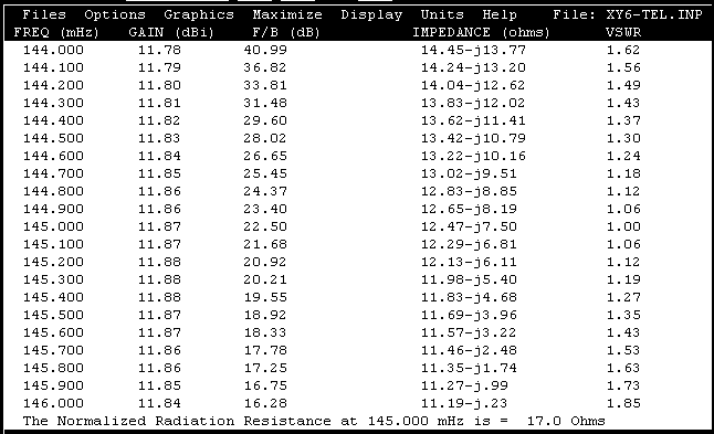 |
The Radiation Resistance on center frequancy (145,000 MHZ) its 17 Ohms. In practice the antenna needs a "matching system" for a 50 Ohms coaxial cable feeder ( H-100, RG-213 or similar).
I have used a "Hairpin" system (FIG. 4), because that is very simple and effective. YAGIMAX antenna design program including a calculation-tool for the Hairpin's dimension, depending upon "data" of the table above (FIG.3)
The Drive Element is an "Open - Dipole" (two pieces of about "Lamda/4")
with overall length 0.961 m. (see FIG.1)
FIG.4 shows the Drive-element (Dipole) and the Hairpin construction on the dipole's plastic box. The gap (spacing) between the two screws is 2.2 cm (dimension B) and the dimension "A" is 4.5 cm for 1:1 SWR (on my antenna).
If you have not the optimum SWR (1:1), you can increase or decrease the "A" dimension a few millimeters, looking for the minimum SWR.
The antenna has been constructed on a 15 x 15 mm aluminium boom and I have used for the elements aluminium tubular rods of 8 mm diameter. The plastic box that I have used for the dipole it was from an old TV-antenna.
Keep in mind: this antenna has a sharp SWR curve in order to be achieve the highest gain. You must be careful with elements dimensions !
The maximum acceptable variation is ± 2% !
Finally, the FIG. 5 & 6 shows the polar-plots of antenna
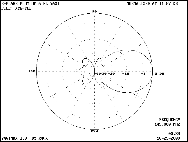 |
FIG.5
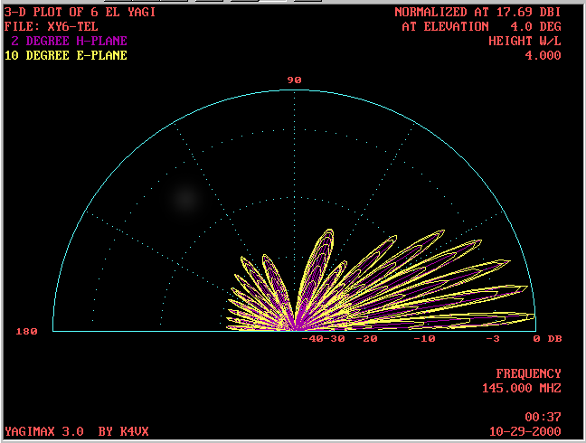 |
FIG.6
Good luck !
Costas SV1XY - Makis SV1BSX
| Comparison Antenna Tests by SV1XY: a)The 6 El Yagi antenna was placed into a 6 m. mast with Vertical polarity. b)The 2nd antenna was a Vertical 3x5/8, also into a 6m. mast (+ 5m length of Vertical). TX-Rx = IC-706 |
|
1. R0 repeater, 130 Km South: receiving 5 S with 3x5/8 Vertical, 9 +20 with 6 El. Yagi. 2. QSO with SV1DFX, 220 Km West: FM, 50 W, 1 S unit. (No sig on 5/8) 3. QSO with SV3AUZ, distance 140 Km South: SSB, 500mW output, 1 S unit.(No sig on 5/8) 4. QSO with SV9CVY, 320 Km South (Crete Isl.): SSB, 25 W, 3 S units.(No sig on 5/8) 5. QSO with SV4/SV1DAY/M, 170 Km North: FM, 50 W, 1-5 S units. (No sig on 5/8) |