144 MHZ to 28 MHZ
2nd Down-Converter for AO-40 Sat
On the "CAL-Ampl 31732" 2,4 GHZ Down Converter" for AO-40 DownLink frequency, it's possible to replace the original Xtal of 8,500 MHZ with a new 8,8125 MHZ.
This way we have an output of DownConverting frequency from 2,4 GHZ to 144 MHZ. (122 MHZ with original Xtal)
 |
By using a second homebrew Down-Converter with an also popular Xtal of 116 MHZ, the final receiving frequency is into 28 MHZ (28-30 MHZ, 10 m band), on HF.
An HF transceiver (or HF receiver) has a superior receiver from any mobile VHF or scanner. Adittional, a good HF receiver
has narrow CW Filter, Notch, (maybe DSP) etc. that are very usefully for difficult receptions, as that of satellite.
FIG.1 shows the BLOCK of this combination.
 |
FIG.2 above shows the electronic diagram of the 2nd DownConverter (Homebrew). The basic component of my DownCoverter is a NE602A. This IC indluding a "Double Balance Mixer" plus Oscillation circuit. On my project, I've no used the Oscillation-Stage as oscillator. Actually, 5th overtone Xtal (like the 116 MHZ) is impossible to oscillate with a circuit like the NE602 including. PHILIPS Electronics describes on NE602A data sheet various infos for a good driving from external Oscillator. The most important point, is the "driving level" at Pin 6. (200 - 300 mV PP).
On my design I've used a typical oscillator for 5th Overtone Xtal of 116 MHZ (circuit from VHF-UHF Manual). The next stage, a BFW92A hi-freq transistor works as RF amplifier, giving an output level of about 1,2 V (on a VTVM with RF-probe). By using a resistor divider (R6, R7) we get finally 90 mV (260mV PP) into Pin 6 of NE602A, which is the optimum value as PHILIPS "Data-sheet" describes.
L1, L2 inductors with the parallel CT trimmers act as filter (input BandPass filter)
and as matching sections. (L1 to input, L2 to NE602A) .
Pin 2 of NE602A is grounded via 1n5 SMD capacitor, for good RF decoupling. The output to NE602-input (Pin 1) is taken from the middle-tap of L2 by using a ceramic cap (C6), so the circuit working as "Single Balance Mixer", for simplicity.
The 116 MHZ signal from LO and the Input RF signal of 144 MHZ both are mixed into NE602A. An output 144 - 116 = 28 MHZ, it can be taken from the Output of NE602 (Pins 4 & 5).
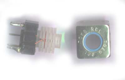
T1 is an RF-transformer on a usual TOKO RCL, to
reject any other Freq except 28-30 MHZ (Band Pass Output Filter). The form of T1 is 5mm with ferrite core.
The primary winding has 9 turns of 0.2mm wire and the secondary 1 turn . The C8 is 18pF, ceramic cap. The coil is not critical. Alternative, an IF 10,7 MHZ coil can be used by removing few turns of primary winding.
The Figure below shows the TOKO coil.
 |
 |
Fig.3
Fig.3 above shows the external view of my converter. Is being constructed into an RF-proof box, from Old TV-Tuner, which is excellent for this project. I've used a BNC connector for 144 MHZ Input and a simple RCA female for 28 MHZ Output
Fig.4 below shows the PCB of this project. It is a small printed board.
 |
 |
Fig.4
On the right picture shows the Components Layout on my PCB. The Zener diode (5V6 / 1W) should be soldered in the down part of PCB, there is not place on the upper side. Actually the printed board has been used also in other DownConverter, with just 6 V supplying, but this unit needs 9 Volts for Oscillator & BFW92 and 6 Volts for NE602.
Another point is the "L" inductor. This PCB has a place for inductor, between Xtal and C13. My 116 MHZ Xtal (from MUS manufacter) works easily without "L" inductor (I'm very lucky guy!).
But generally, a 5th Overtone Xtal oscillator is very-very wayward... if you have not oscillation, it should be tried by adding the "L" coil. By using a similar coil-form like T1, begin wrapping 2-4 turns on the coil form. My experience they is, that needs enough experimentation till the right oscillation.
Without coil, a short-link wire should be connected between the two pin-holes of L coil.![]()
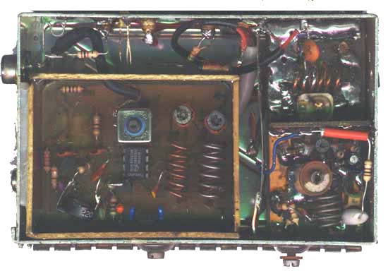
Fig.5,6 below shows internal views of my converter.
 |
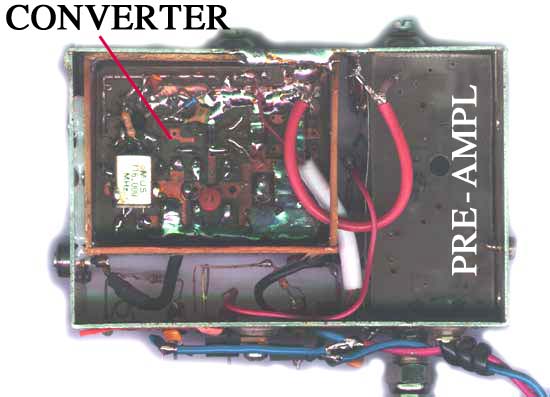 |
On my construction I 've used a good input preamplifier, as the one that I have described on my Homebrew page following by the NE602 circuit. ( Fig.7)
The pre-amplifier is not necessary, if the gain of 2.4GHZ is high enough and perhaps this overdrives the
HF receiver, especially if that is very sensitive. So, you must trying without pre-amp and if you need
higher amplification, then is necessary the pre-amp stage.
Below shows the Complete Block-diagram of this unit. Including an RF - PreAmp,
the DownConverter and the Power Supply "plus" the DC-Injection stage. The DC-injection is necessary
for DC-Voltage supply of "CAL AMP 2,4 GHZ Down Converter".
 |
Have Fun
Makis SV1BSX (May 2003)