Nowadays the AO-40 belongs to "dead birds", but this antenna definitely is useful for any other Satellite like LEOs and also for the next HEO-Sat P3Express which expected to be placed in orbit during 2007.
The design of my Homebrew 10 El. UHF Yagi is based on DL6UW Yagi antenna's design-formula. In my page you will find several details of manufacture, additional infos, construction details, Polar plots, Gain tables etc, from "YagiMax" Antenna-design program. This antenna has been selected due to small overall size of Boom vis-a-vis to achieve Gain, offering the optimal result for Satellite and terrestrial communications.
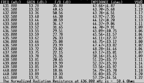 |
Fig1 shows a table about Forward Gain, F/B, SWR & impedance vs Frequency created by Yagimax program. The Forward Gain is 13.6 dBi (about 11.5 dBd) and it's pretty small, about 1,5 m in length. In addition appears the optimal 50 Ohms impedance at 436 MHZ, pretty perfect for Satellite operation. This way the connection ("matching") with a second identical crossed-Yagi antenna is easy job, just by using the usual 75 Ohms ![]() "Matcing Stubs", without problems and troubles like other Yagi-antennas with unusual impedances.
"Matcing Stubs", without problems and troubles like other Yagi-antennas with unusual impedances.
That is a great advantage for those who are interested about Circular polarizarion antenna systems.
|
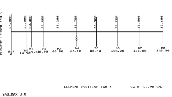
FIG.2. below shows the dimensions of Yagi antenna.
 |
Keep in mind, this antenna offering ideal relationship between length & Gain... for 3-4 DBd more Gain we need in practice about a double Boom (in length) and much higher number of Elements. So, it's very practical to keep the antenna as small as possible but on the other hand with high enough Gain, like the 11.5 DBd of this Yagi antenna. Also, a small antenna like this it's definitely a good choice for a portable system. The small length of antenna allows us to place it easily in the port-package of our cars together with a small Dish (ie. 60cm Offset) for S-band, in order to cover the U/S Mode as that existed on AO-40
and probably it should be necessary again after the P3E launch, "plus" the old Mode-B (U/V now).

![]() Construction
Construction
The antenna is being constructed into a 15x15 mm square-tubular aluminium Boom. For the dipole (only) I've used
8 mm tubular aluminum rod. All the rest Elements (including reflector) are made from 5 mm
aluminum rod.
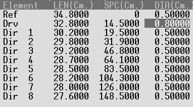
Is very important for the antenna to maintain right diameters on Dipole and Elements. Also the distance (spacing) between the elements is critical. (See Table below). Keep in mind, these dimensions are correct when the BOOM is metallic (15x15mm square aluminium) and each element is placed directly onto the Boom without isolation.
If you want to use a non-metallic Boom (ie PCB tube), under this construction method each Element (isolated from the Boom) must be shorted by 8mm, except the Dipole.
 |
The antenna needs a "Bracket" for mounting into the Mast. The Bracket take place behind of reflector and Never - I repeat NEVER, between Elements! For this reason the Boom is a few Cm bigger than 148.5 Cm.
If you want a center-point Bracket, that is possible but under this condition the Mast should be not metallic (at least 1m long). However, is highly recommended a supporting-point behind of reflector (back-supporting).
![]() The Dipole
The Dipole
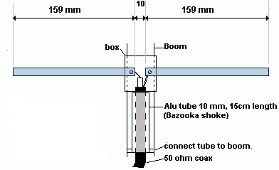 |
Fig.3
Fig.3 above shows the Dipole's details.
The Dipole should be isolated from the Boom, so it's necessary a plastic box. I' ve used a TV antenna Dipole's plastic Box, in order to support the Dipole and keeping that isolated from the Boom.
All the rest Elements are connected into the Boom without isolation as above mentioned. I' ve used small aluminium-stripes in order to support the elements into the Boom. Additionally I have drilled each element precisely at the center-point. I have passed a small screw (or rivet) through that hole in order to support and secure the position of each element onto the boom (Fig.4, 5 below).
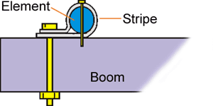 |
A second screw (or rivet) is passed through the stripe and Boom. Thus, the mechanical construction is pretty good, the antenna is very robustious against winds and storms.
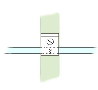 |
The Bazooka !
The Antenna uses a "Bazooka" tube on feeding- point between "Balance dipole" and "Unbalance" Coaxial cable. Keep in mind, the "Bazooka" tube is connected electrically with Boom on the side close to Reflector by using a metal stripe (or corner) and also with the "outer shield" of Coaxial cable at this point.
Fig. 6 below shows another view of "Bazooka" construction.
 |
Fig.6
The "Bazooka Tube" is being constructed from copper tubular rod 10mm (1 cm) diameter (ie a piece of copper water-pipe). The length of tube is 15 cm.
The coaxial cable passes through the Bazooka-tube and then connected into the Dipole. At the input of Bazooka (close to reflector) the outer-plastic cover of Coaxial is stripped (about 5-7mm). In this point the outer shield of Coax is soldered together with Bazooka-body. Alternative, is also possible to solder permanently at this point a chassis N-type female connector.
This dimension of Bazooka's tube is good enough for RG58 (not recommended for UHF, except a small piece around rotator) or a much better but still enough flexible Coaxial like "AirCel 7". In case you have a wider coaxial, like AirCom+, RG213, H100, etc, the diameter of Bazooka tube must be larger, i.e 15mm, but the
overall length of it remains always the same (=15cm).
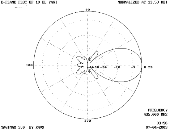 |
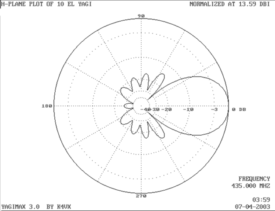 |
Figure 7
Figure 7above shows the E-plane & H-plane of 10 El. UHF Yagi antenna.
![]()
Using on U/S Mode (AO-40 UpLink)
I've used this antenna with Vertical polarity on both systems for AO-40, portable and fixed. For portable use, I've used a Kenwood TR-9500
UHF All-mode Mobile transceiver, with just 15-17 Watts Output (modified, it's only 10 W from Kenwood).
The coaxial cable between TX and Antenna was not too long, about 1.35 m (3 Lamda x VF*), in order to be able to keep the losses, as low is possible. By using this "setup", it was possible to make a lot of QSOs "via" AO-40,
as Portable station. The Effective Radiation Power was about 150 Watts
(15 W of TX-out x 11.5 DB Antenna Gain "minus" 1-1.5 DB of Coax & N-type connector).
*VF=Velocity Factor, 0.66 for RG58, RG213 etc.
On my fixed station I've used the same Transceiver, but I've a long-long Coaxial cable (4-5 DB loss) from my Shack up to my UpLink Antenna. Thus, It was not possible to feed my 10 El. Yagi with high enough Power, to achieve the recommended ERP.
Solution: I was using a small UHF-Linear Amplifier, behind of Antenna, very close to Dipole. This way, it was possible to keep the Losses as "Low" as possible between UHF - PA & Antenna, because the Coaxial cable was just a few Centimetres. The UHF-PA had a Gain of about 6-7 DB... so, if the input is supplied with 5 Watts, the UHF-PA output rose at least 20 Watts x 11 DBd of Antenna-gain for a total of about 200-250 Watts ! (Good old days with.... AO-40 !)
This antenna is not just for Satellites Uplink. It's also an excellent antenna for any terrestrial use in UHF Band, as the "V SWR" is quite low between 430 - 440 MHZ.
That's all folks - Have Fun