"Aquarius" day after day.....
After some time of no building activity, the dark afternoons and less busy week-ends has come finally. Perfect time of the season to build a new rig. See what is being done on my bench.
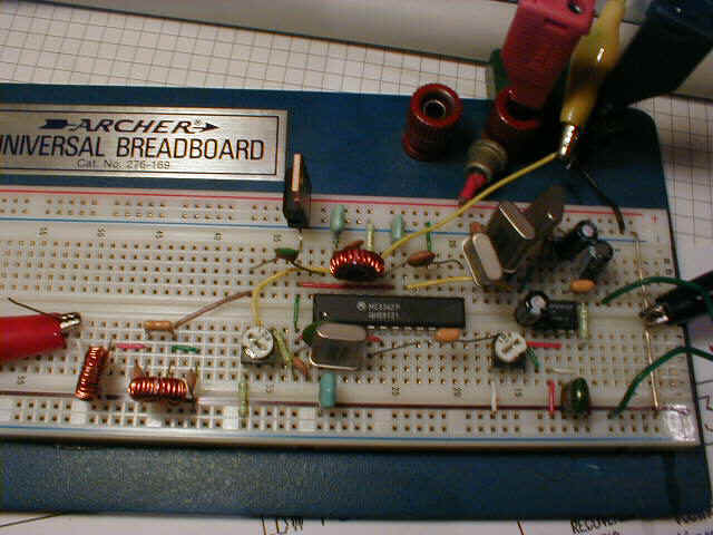
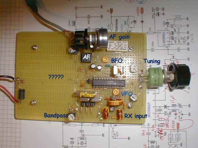
This is very prototype RX part of new 80M CW QRP rig.
I like this way of start, because of easy modelling a components layout. Say, that's enough experiments with NE612. The heart of the receiver is popular Motorola chip MC 3362. Not much Ham applications are available. That's my pleasure to go.
I had a great fun soldering a board upside down. That's even better than Manhattan style.
This is very convenient and gives opportunity to select best circuit, best value and best component. I have changed IF frequency as well as VFO frequency triple times. Finally remained on 8MHz RF and corresponding VFO, which seems to be very stable. I don't have final schematic because there are so many ways to develope.
Up here you can see the working prototype ( ugly assembly ;-))) ) photo.
First contacts were made 15th of November during local contest on 80m.
I made 21 QSOs and RX worked fine in QRM and pile-up. Output power reached 3W
25th of November update
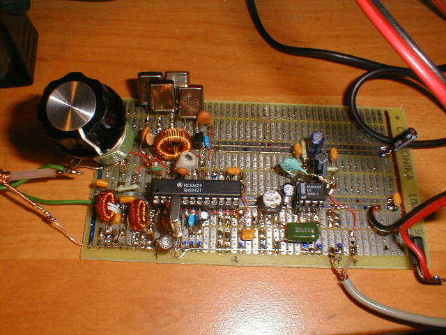
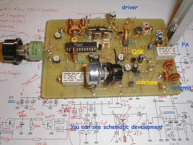
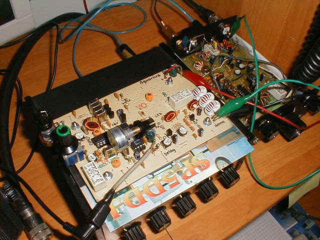
Up here you can see the next step of prototyping.
My favourite "universal breadboard" has changed into protoboard, but I am trying to develope future printing circuit based on above "training". Every component is carefuly selected and placed. Schematic diagram is corrected in parallel.
Just a day before CQWW DX Contest update
80m meters RX is working finally as good as I wanted to. IF = 8MHz, VFO = 4,500kHz - 4,400kHz
The biggest problem was the VFO stability. I had to recall experience of many Hams and myself to find a solution for drifting parameters of coil, capacitors and IC's internal varactor diode. Compensation wasn't easy but finally I used poly cap, T50-6 ( yellow core works better than red) and ceramic trimmer capacitor. The overall drift is very low. 170 Hz within first 5 minutes and less than 50Hz in following hours. I tried varactor tuned four crystal ladder filter for the first time. Works fine
Now let's go contesting ( 10m probably if opens)
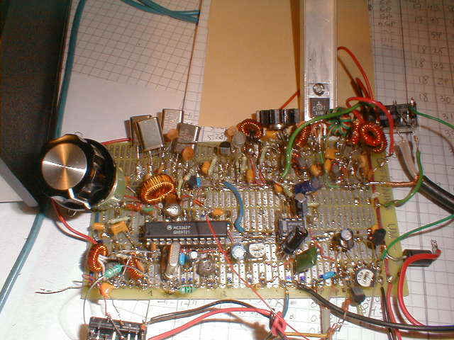
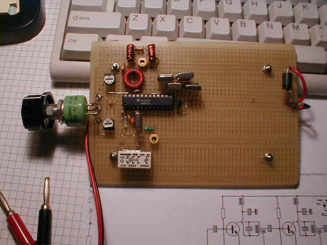
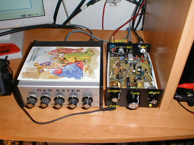
The Contest ended with satisfactory score - 312 QSOs, 34(!)zones and 82 countries only. This counts for 95k points. Just after the contest I decided to eventually finish prototyping and commence PC board project for future kit. Below you can see working prototype-clean. I worked OK1DSS today (11th of December) receiving solid 579 report. Sigi from Desna hasn't problem copying all QSO data, so did I.
Working prototype
ARRL 10m Contest failed and I spent week end mostly on mechanical work, putting a board into metal case. All rig measures WxDxH - 100mmx140mmx50mm. After wiring all front and rear components and plugging a 13,8V DC everything appeared to be mute. That was a thrill, because both protoboards worked fine. Couple of minutes and short cut in headphones socked cleared everything. New problems appeared instead. This is my probably last attempt to build RF project on computer based predrilled boards. Too many stray capacitances ( antennas ! ), poor grounding etc. The next step will be a home brew PC board with rather different components layout. Anyway, another contacts were made confirming that 3Watts is enough for 80m Europeans and finishes the author's job. I was thinking of the name of this rig. How about " Aquarius-80 " ? - which obviously refers to my personal astro sign.
One "whistle" is the LED on the right bottom corner. Glows green on receive and red on transmit.
Schematics will be provided later on when true PC board will be developed and tested.
By the end of the year update
Last days including Christmas I had few days off which were consumed for continuing the project.
I drew a serious PC Board using simple software from Express PCB. This was my first trial, and after couple of hours I made it. The picture of PCB was exported to Corel Photo Paint for adjustment and printing on the foil. Using thermotransfer method and house iron I broke two sheets of foil, but third came quit good requiring minor corrections. Drilling more than 100 holes produced nice blister on my hand, but that was really worth it !.
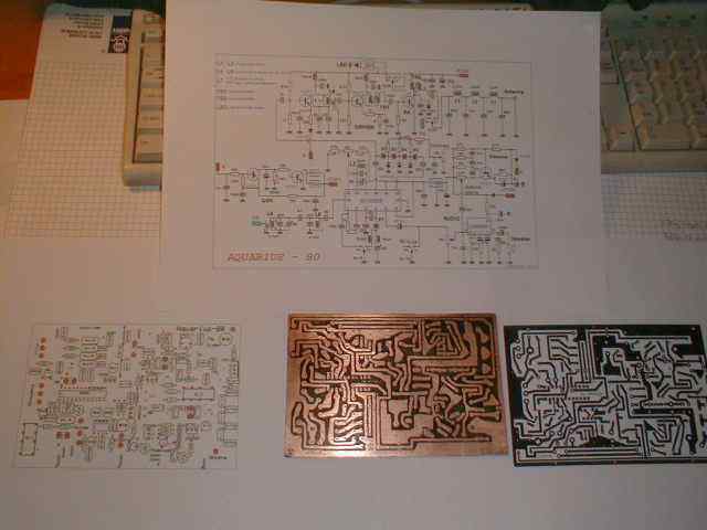
Board measures 135mm x 90mm only and will accomodate approx. 119 components
Today ( 30th of December) I successfuly assembled RX side, QSK and sidetone, writing "step by step" manual in parallel. This will help someone easy assembling of the rig. Let's suppose in one week-end ;-))
Partially assembled board of "Aquarius" #001 lying next to working prototype
So far so good. Only one track comes to nowhere ;-))). Tomorrow or the day after TX side will be played.
First of January 2004 update
New Year has come with light snow and completely assembled "Aquarius" board. No problems appeared and my newest rig could produce clean 5W output signal. The first QSO is always a great moment in Ham's life. This time the first contact was made with Guyla HA7JCA from Szentendre. He gave me 589 with no negative comments on signal quality. So, after several weeks another rig became alive. What is to be done: packing into case, homebrewing front panel silkscreening and that's it.
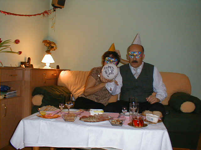
Mirka SP5NHF and I are celebrating New Year
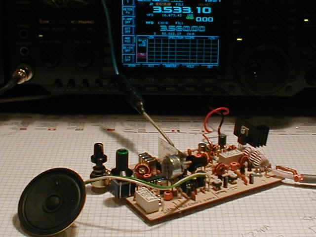
"Aquarius" right after first QSO on 01.01.2004 at 1941 UTC
And the day has come...
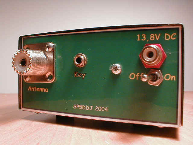
The rig reached it's final look. Why front and rear panels look so fine? I found very simple method for homebrewed silkscreening. The graphic project was prepared using Corel, then printed on photo paper and laminated. Crazy glue helped attach plates to front and rear and that's it. First warm-up showed no significant difference between board working alone and mounted in a metal case. The only one problem was that I missed one Watt. That was caused by rear metal panel to which PI-filter was too close. Little adjustment and legal limit of QRP is again on dummy load. You can see photos below. Isn't she lovely ?
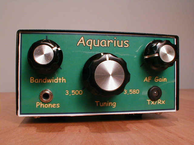
"Aquarius" - front view
"Aquarius" - rear view
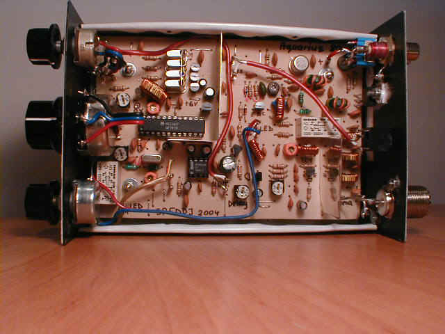
"Aquarius" - inside view
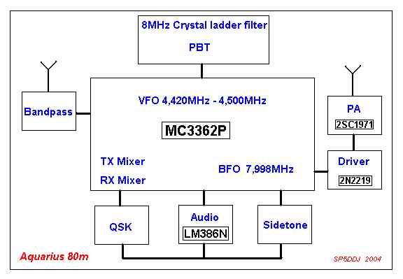
"Aquarius" - block diagram
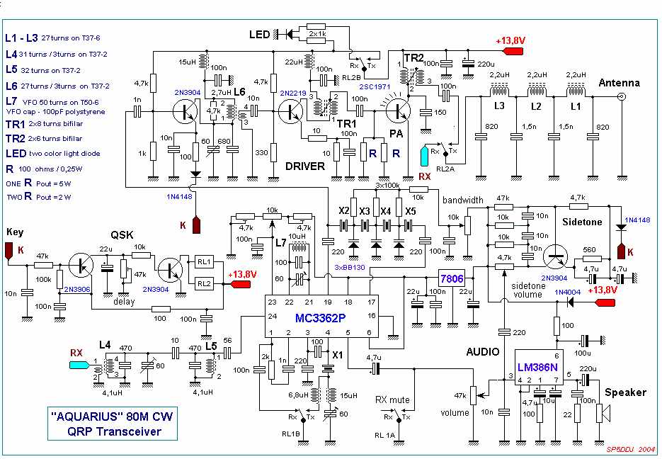
"Aquarius" - schematics
No |
Date | UTC | Band | Callsign | RST sent | RST rcv'd | QSO Data |
| 1 | 01 Jan 2004 | 19:41 | 3,5 | HA7JCA | 589 | 589 | Guyla, Szentendre |
| 2 | 03 Jan 2004 | 23:01 | 3,5 | DL7PP | 589 | 599 | Tom |
| 3 | 04 Jan 2004 | 19:21 | 3,5 | UA6YGN | 579 | 579 | Roman, Maikop |
| 4 | 07 Jan 2004 | 16:07 | 3,5 | DK0WAL | 579 | 579 | Ray, Doebeln |
| 5 | 12 Jan 2004 | 19:58 | 3,5 | G3ZRJ | 569 | 479 | Tony, Collow |
| 6 | 24 Jan 2004 | 20:35 | 7 | EA6UN | 579 | 579 | Jurek |
| 7 | 25 Jan 2004 | 15:30 | 3,5 | SP4JFR | 599 | 599 | Bolek, Ketrzyn |
| 8 | 26 Jan 2004 | 19:12 | 3,5 | S58MU | 579 | 559 | Mil, Loka |
| 9 | 01 Feb 2004 | 17:55 | 7 | ER5ER | 579 | 579 | Yuri, Kagul |
| 10 | 08 Feb 2004 | 19:25 | 7 | UA9MDU/3 | 589 | 579 | Slava, Moscow |
| 11 | 10 Feb 2004 | 20:32 | 3,5 | DL6SRD | 569 | 579 | Roland, Stuttgart |
| 12 | 15 Feb 2004 | 17:12 | 3,5 | SP9LVZ | 579 | 569 | Piotr, Wola Aquarius #002 owner |
| 13 | 21 Feb 2004 | 04:16 | 3,5 | K1XM | 5995 | 599MA | ARRL Contest |
| 14 | 21 Feb 2004 | 04:19 | 3,5 | VY2LZ | 5995 | 599PEI | ARRL Contest |
"Aquarius" - LogBook
This concludes "Aquarius" story.
The sequel #1
Some of my Ham friends asked me If I could convert "Aquarius" to 40 meter band. Being busy at work I took a challenge anyway. Two weekends and here you have. List of necessary modification is shown below. But, do not promise great results to yourself. Remember that simplicity of Aquarius leeds to many limitations. However, good experimenter could manage it !
40m version is tested - see clean CW on the 756PRO scope
40m version is fully assembled
40 meter version details:
1. VFO tunes from 4960kHz to 5000kHz. L6= 8,1uH -> 45 turns on the same core (T50-6)
2. RX bandpass filter L4 and L5 are the same. Parallel C=100pF, serial C=2,4pF, add trimmer cap 60pF to L5
3. Crystal ladder filter 4 x 12MHz, coupling capacitors changed from 220pF down to 150pF
4. BFO - serial choke 15uH changed into 4,7uH, and 6,8uH into 2,2uH respectively.
5. Output filter (PI) L1=L2=L3 = 0,9uH -> 15 turns on T37-2. Capacitors: 470pF, 1nF, 1nF, 470pF
6. 2N2219 emitter resisor ( non blocked by capacitor) changed to 5 ohms ( more drive required).
7. L6 the same, parallel C=150pF instead of 680pF.
The sequel #2
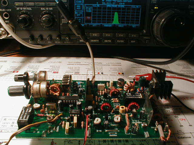
Popular and only CW Ham band couldn't be omitted, and right after 40m version new development appeared. Unfortunately IF=4,43MHz and VFO produced too low output after mixing, so simple board was added. But the four crystal ladder CW filter works even better than 8MHz one.
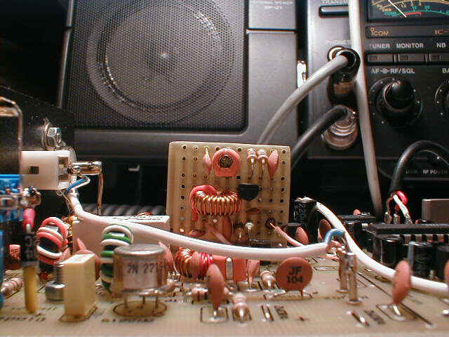
This very small PCB is glued to the main board
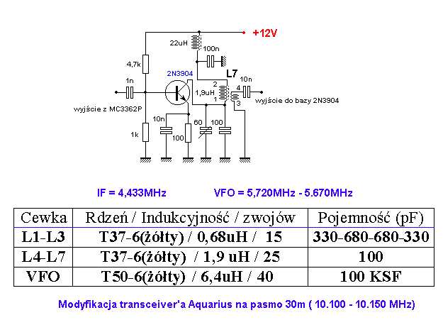
This is a diagram of additional circuit. The text is i n Polish, but no problem I suppose
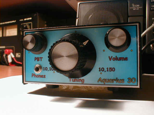
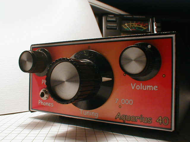
Aquarius 30 final look
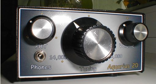
Aquarius for 20m band
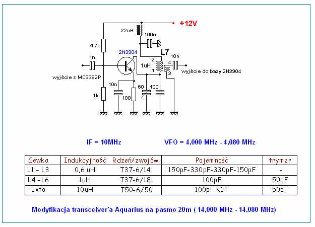
Aquarius 20 requires additional circuit in TX side.
The text is i n Polish, but readable I think
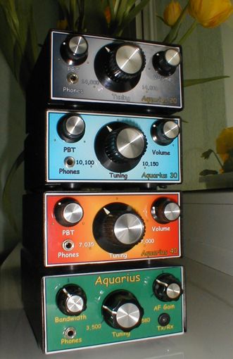
Four Aquarius'es
From the bottom: 80m, 40m, 30m, 20 versions
Last but not least Aquarius was made for one of my Ham friend
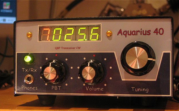
This "almost C-line" rig is equipped with digital readout and more selective receiver front-end.
This concludes Aquarius project
New project of CW transceiver is on the way