K-1 story
K-1 is the CW QRP transceiver kit designed and distributed by Elecraft Company
Once upon a time my XYL asked me - " What would you like to have on your 50 birthday ? " The answer wasn't easy, but after a couple of hard thinking days I said - " How about K1 ? " - Mirka SP5NHF agreed very fast and I soldered this cute baby-rig having the best enjoyment since my first QRP rig has been developed in 1995.
Now You can see my K-1 from the package to first contact
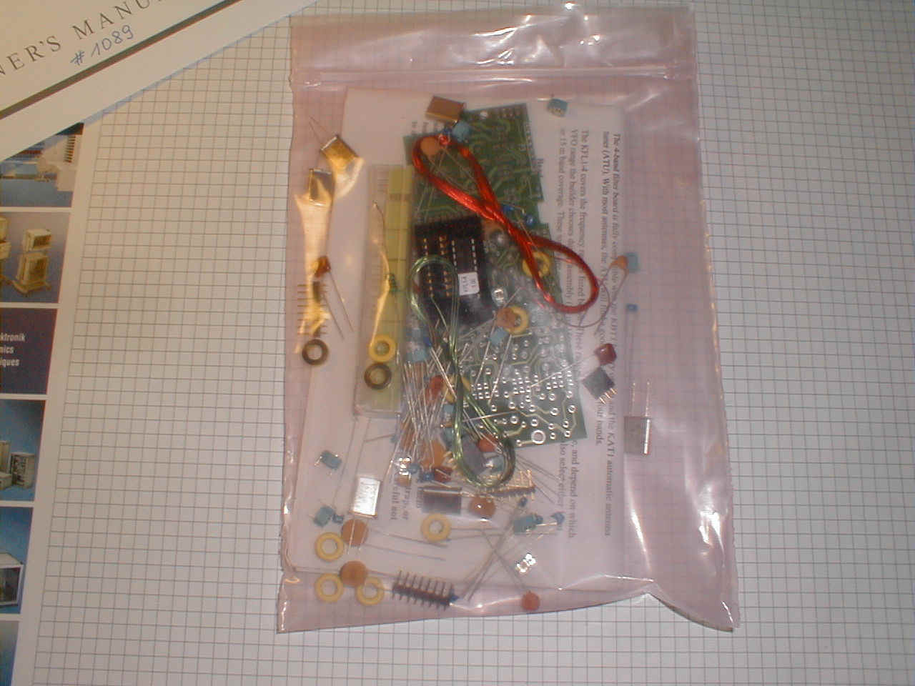
This is what you get in the package. All components are collected in logical groups in labelled envelopes.
What you have to do first is to read "Owners Manual" several times and accept the way of assembly given.
I recommend to download manual from the Internet and study while waiting for the postman's ring.
If you assembly K1 " my own way " despite of manual you'll regret it very much.
Exceptionally I've started with front panel assembly, but manual prefers you to solder filter board first.
I simply could't resist myself to see the face of K1 first. Beginners - don't follow - me, please.....
 T
T
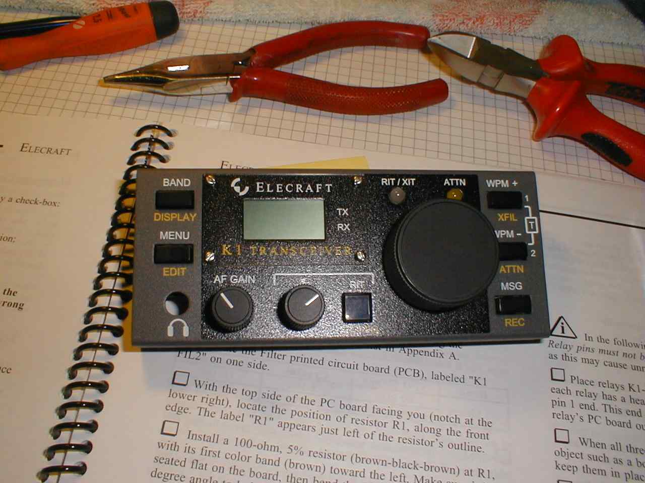
Front panel board is ready - front view
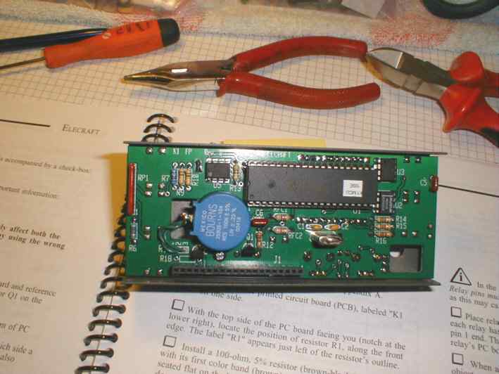
Front panel board is ready - rear view
Construction hints:
1. Mark top board and bottom board using permanent marker
2. Solder S3 from the top side of the board
3. Consider installing diodes D1 and D2 BEFORE soldering U1 socket and U5
Filter board (KFL-4) package
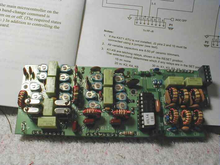
Filter board is ready - top view
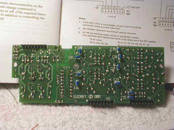
Filter board - bottom view
Construction hints:
1. Don't miss that you have to install T3 and T4 before you will install T1 and T2 !
2. Secondary turns of T3 and T4 shall be very well prepared and carefuly soldered
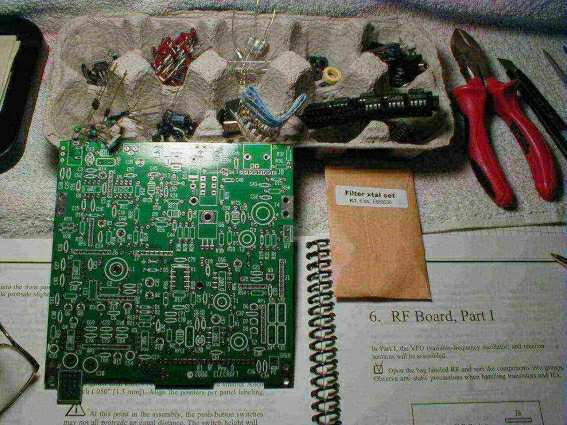
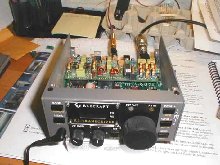
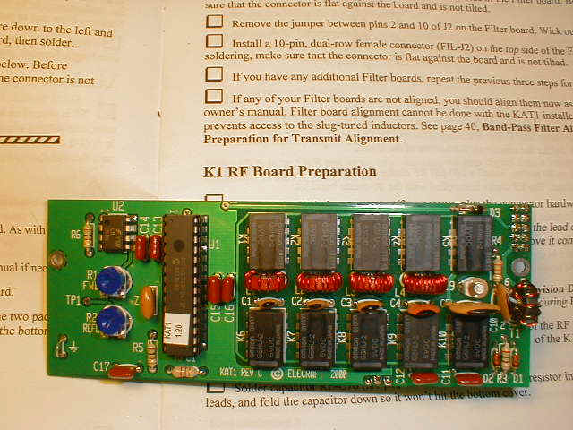
RF board before soldering. All components are groupped in the egg carton.
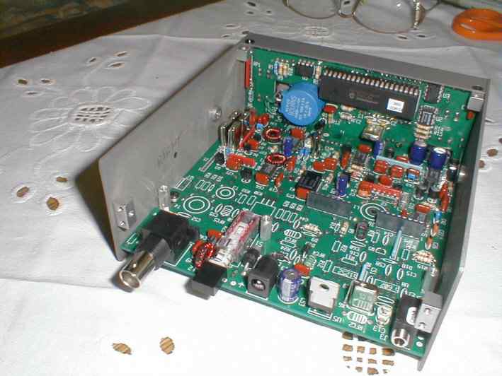
RF board is partly assembled and ready for the RX alignment and tests.
Construction hints:
1. Use transparent tape for temporary fastening K1 relay before soldering. Use the same method while soldering other relays and angle connectors
2. When securing VFO coil beware of delicate nylon screw. Don't screw too hard. Cover VFO coil with couple of layers of nail paint. This will prevent VFO coil against floating.
3. Double check all soldering points using glass magnifyer before running alignment tests.
4. K1 is rugged but delicate rig. Handle assembly with care and always read (!) notes twice.
Receiver started for the first time flawlesly, but I have to learn fast how to use multifunction switches.
What a nice sound !
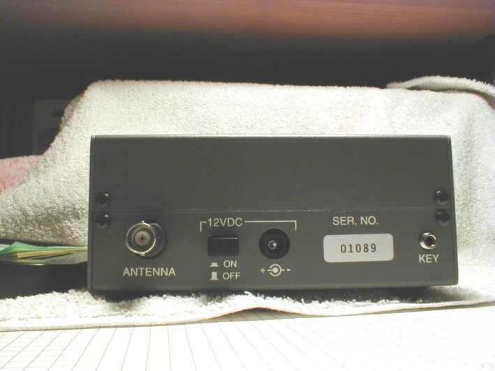
When transmitter section was soldered and aligned I proudly stick a serial number onto rear panel.
Construction hints:
1. Installing speaker put a small fibre material between case and speaker to prevent from dust.
2. If necessary instal optional grounding connector on the rear panel ( I didn't do it so far )
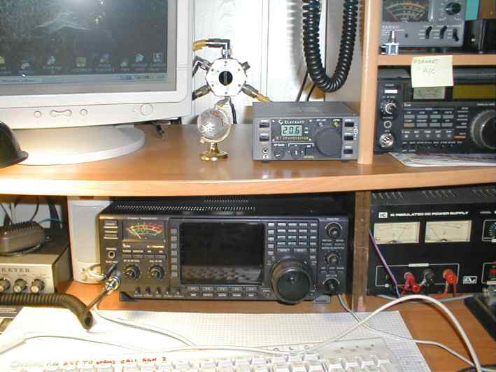
On the spot in the radio shack. Compare the size to IC-756 PRO
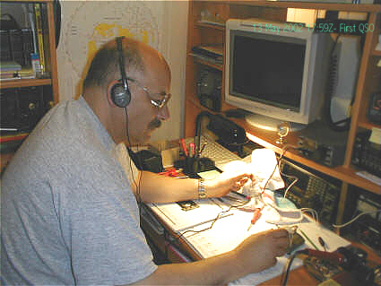
During the first contact on 40 meters with OH2LBK on 13th of May 2002
# 1089 is alive and hits the waves !!
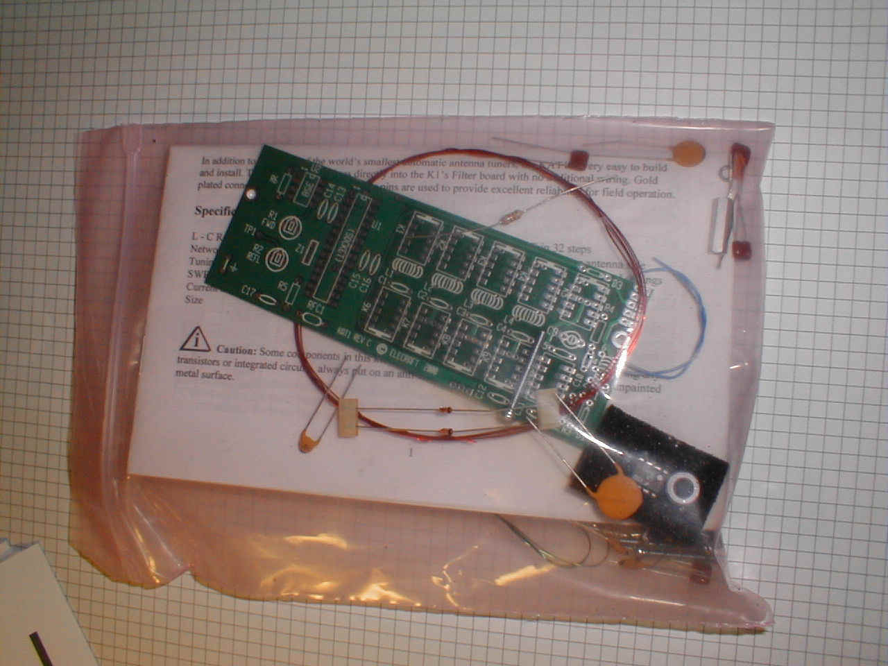
This is KAT-1 internal antenna tuner package
KAT -1 assembled with firmware 1.20
Ready for test with newest firmware 1.3
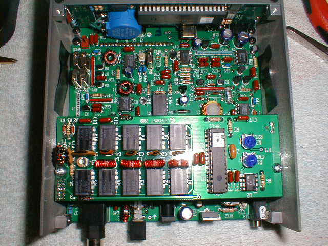
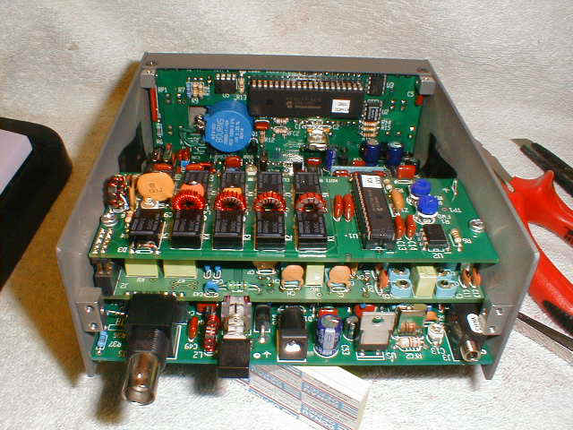
Top view before closing
Construction hint:
1. Cut all legs very short. Remember that KAT-1 almost lies on KFL and there could be bridge between. To avoid this problem cover crystals of KFL with the PVC tape ( two-three layers)
Even K-1 could fly........