SOFT START by EMTRON
Every malfunction besides the dark side has also the bright side.
The dark one is obvious - nobody likes problems the bright one is the opportunity to learn how things are working.
One may be surprised how much new knowledge may be obtained once you have to deal with the problem.
Soft start malfunction in my DX1b forced me to study the scheme of this circuit and analyze connections/wiring.
Surprisingly I discovered that:
- Emtron DX-1b being in Off stage (Power switch in Off position) does not mean that Dx1b is disconnected from the mains.
Power through fuses is connected to the soft-start board (electronic components are always under power) and from one side to the transformer and Fan.
The brake in connection is on Triac which being in the blocked stage (in Neutral wire) prevents Transformer and Fan to be feed.
Emtron solved this ON-OFF function like in TV sets where certain components are in permanent readiness ("ready to act").
TV's Stand-by mode however is signaled by a small red LED but Emtron does not have any signs that it is connected to the power line...., it is completely dark.
So, if you do not wish to keep the amplifier in a "stand-by mode" unplug it from the wall socket.
Note: in line with On-Off switch a micro-switch is placed which is active when the cover of PA is in place. Removing PA's cover will open the micro-switch and set the amplifier OFF.
- It is possible to use Dx1b without soft-start - advised by Rudi from Emtron, but not the bigger ones as Dx2 and up.
What you have to do is disconnect Triac's BROWN wire from the board and connect in this place the BLUE wire which coming from Fuse.
Of course, ON-OFF switch in this case is not operational - once you plug PA in the socket wall it starts working. To switch off - unplug it.
- Exploring the possibility to repair this soft start myself, I found the scheme of Emtron Soft Start Board Rev.4 - looking as Emtron design.
I quickly noticed that the scheme has two errors:
1 - on scheme Pin 5 of the TDA 1085C is connected through the switch ON-OFF and resistor R9=9k to the 230V AC (against the Motorola TDA 1085C Basic Application Circuit) but in reality,
is connected to Vcc PIN 9 app.15V DC (as in mentioned the Motorola Info)
2 - on scheme Pin 12 is connected to Pin 14 and both 12 and 14 through C7 to the ground.
In reality Pin 12 is connected directly to the ground.
I have no idea what would happen if Pin 12 is connected to Pin 14 as on scheme but connecting Pin 5 to 230V AC would create disaster.... am I wrong?
- Operating manual is showing that Fan is connected to 120V Pin on the Transformer - in my Dx1b Fan is connected to the same soft start's PINs as transformer is - to the AC mains (230V).
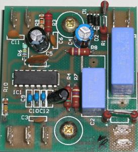 This is a connection scheme of the Emtron soft start board.
Photo of the soft-start board is placed next for easy reference of PINs and other components.
This is a connection scheme of the Emtron soft start board.
Photo of the soft-start board is placed next for easy reference of PINs and other components.
back to radio shack---back to My experience with Emtron Dx1b