OM3BC tracker info
Some extended information about the OM3BC tracker found here: www.om3bc.com/docs/payload/payload_en
Some extended information about the OM3BC tracker found here: www.om3bc.com/docs/payload/payload_en
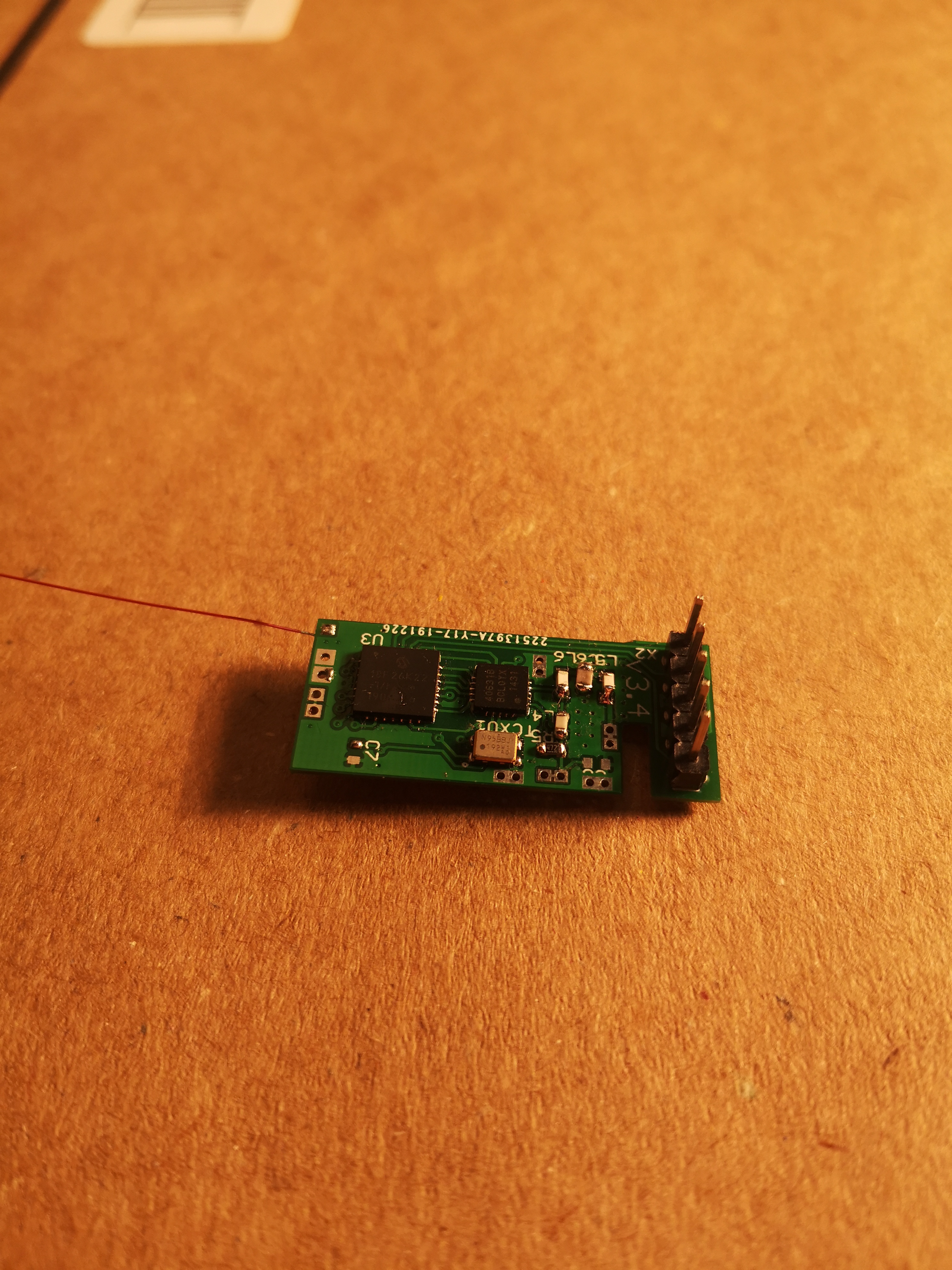
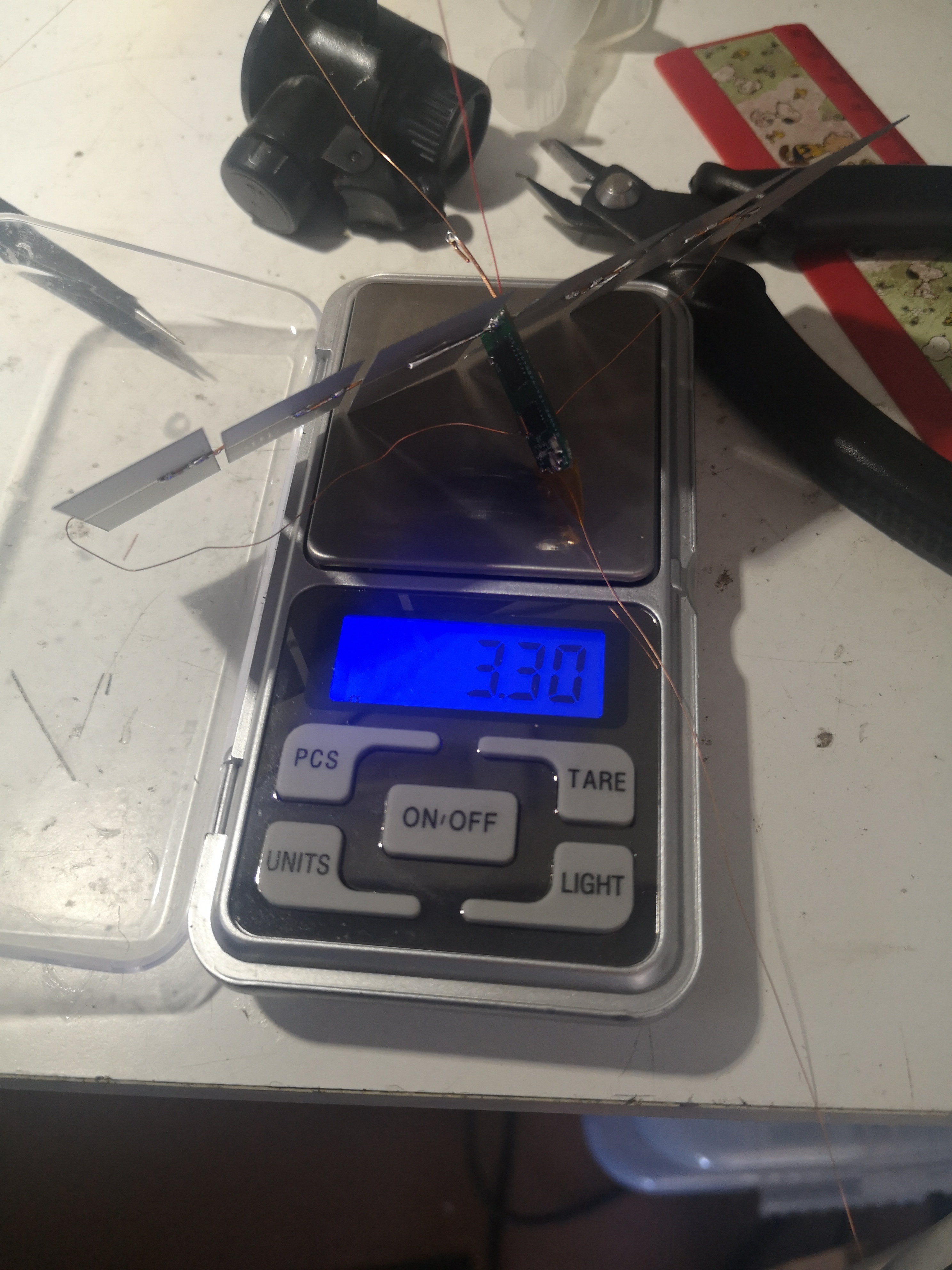
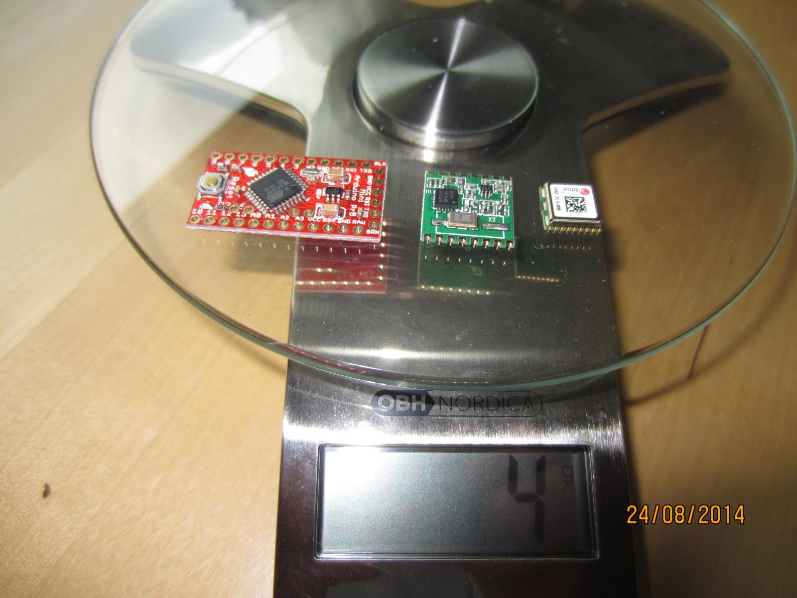
My aim of the Eagle files is to make an as simple to build, cheap and light tracker as possible, a fully assambled board should weigh in on about 1 - 1.3gram,
a fully assambled board with solar cells and antenna about 3.5gram
Im using 6 of the smallest avalible (19x39mm) solar cells in series to power the board, it makes it run from and to 15-19° solar angle dependig on Gps used
After more then 25 launches over the years and probably more then 10 pcb revisions I have come to this final? design, the intention of this page is to ease the building and configuring the OM3BC APRS / RTTY / CW tracker.
The rar file below contains all files mentioned in this small writeup
There are two different firmware versions depending on what Gps module you intend to use:
fw7.5 should be used with Ublox Max modules, I have so far only tested the Max7q and Max7c both working well,
the low voltage "c" version getting a bit longer "runtime" due to its lower voltage demands, Max 6 & 8 should work just as well.
fw14 should be used with ATGM336 Gps which is a "new" cheap module that can be found for around $3 on Aliexpress,
there is no flightmode that needs to be set on this module, it have been tested to over 32000m at the time of this write up.
You will also find Eagle pcb files in the rar for two types of PIC ic footprints.
I have tested both the L version and LF version of the PIC but could not see any advantages using the low voltage (LF) version of the ic
All versions of the si4x6x I have tried have worked well, so far I have tested SI4060, 4463 and 4063.
THE MOST important setting to get reliable startup of the board is to enable the Watch Dog Timer (WDT) you set all as 1:s as in the below picture.
To do this you press the "Configuration:" in the PICkit3 before you program the board.
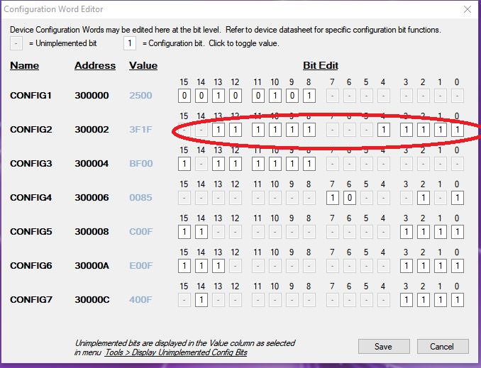
You can read about the fuses in the pic18f26k22.pdf (rar)
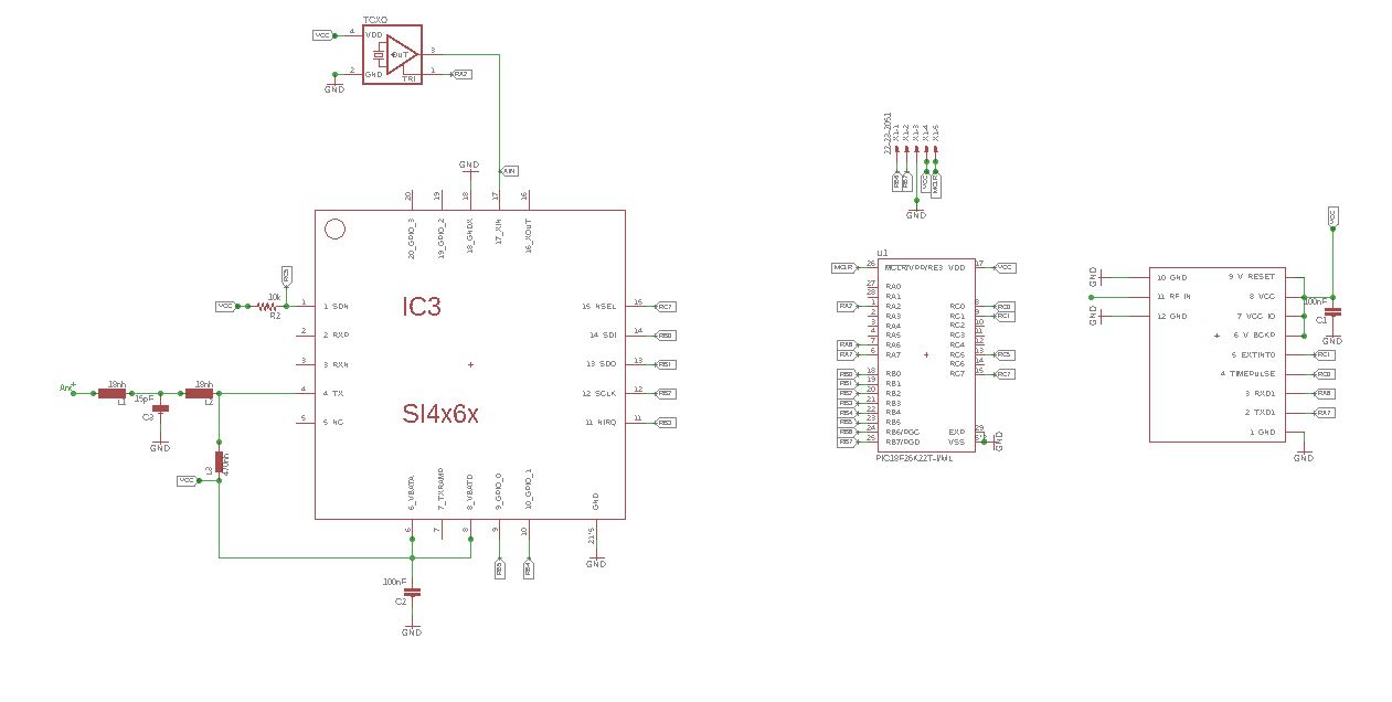
Schematic
Settings Im using:
MYC SA6BSS-9
DEVIATION 425
POUT 8 (pout 100 using 4060 // pout 8 = 25mW on a 4x63)
APRS on
HOLD 2
TAIL on 2
INTEMP yes
REF 19199985
UBLOX on (=atgm336)
TTEXT RTTY 434.5/100b7n2 Temp:\W Gps:\B
UNPROTO APRS V wide0-0 // = to not use digipeaters, leave unchanged if you want to use digipeaters
RFRQ 434500000 // putting the rtty up in ism band
Im using Termite terminal to setup the board, this as well as well as the PICkit3 is in the rar, termite also supports macros so you dont have to enter every setting everytime you setup a new board.
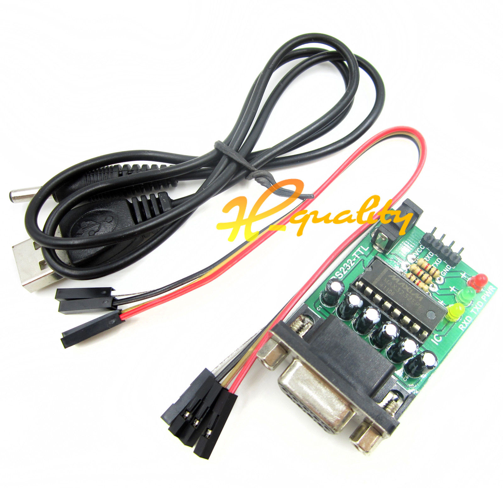
When you configure the board you have to use a rs232 programmer, the only one so far that works reliably is this type, look for it on ebay or aliexpress,
should cost arround 3-5$, note the DC jack, electrolytic caps and LEDs
The voltage out from this is 5V, to reduce this you can put 2 diods in series on the VCC to lower the voltage to more reasonable levels, or preferably a 3.3V LDO.
Schematic
Here is the rar-file
///////////////////////////////////////////////////////////////////////////////////////////////////////////////////////////////////////////////////
Page about PicoTracker and my Homebrew Tracker project: Ultra-CheapoHelp and hints to get the picotracker from hamshop.cz going
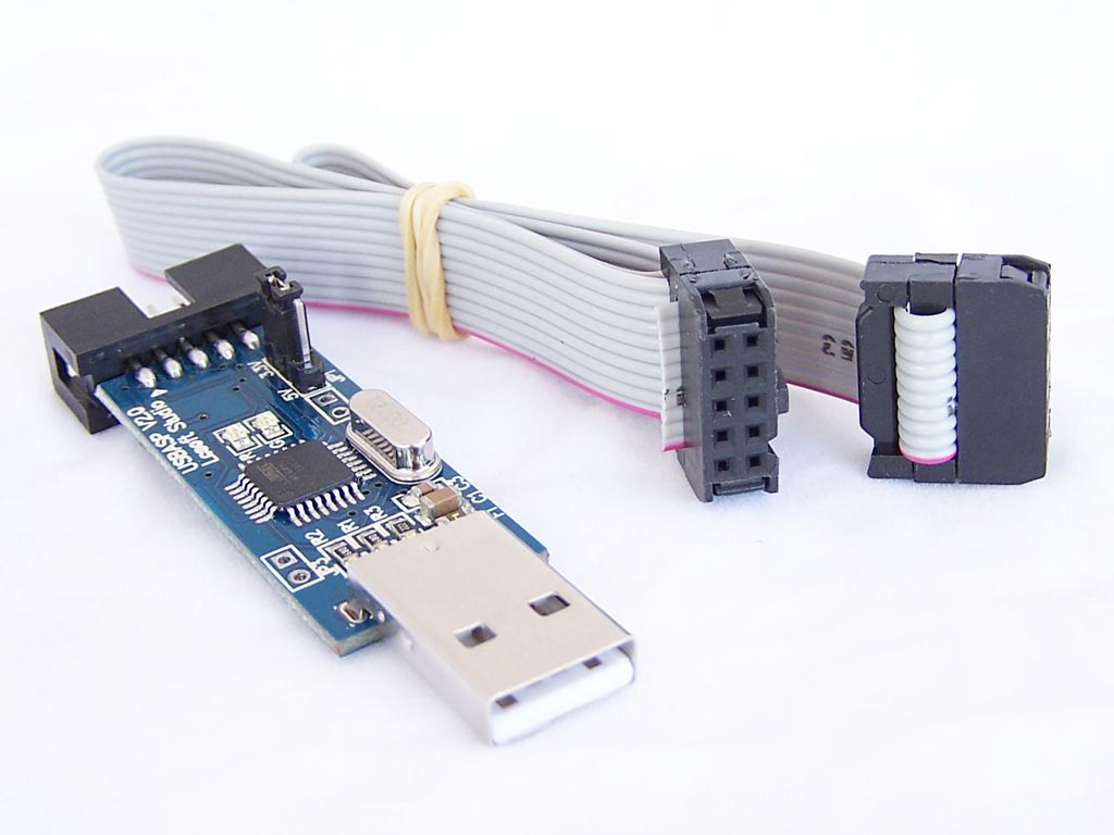
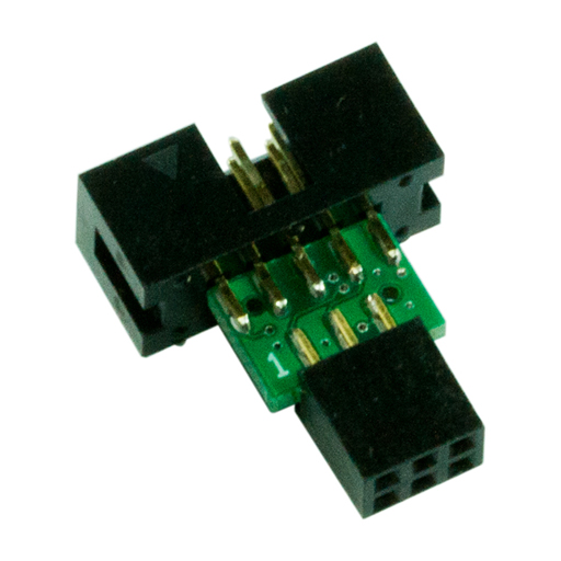
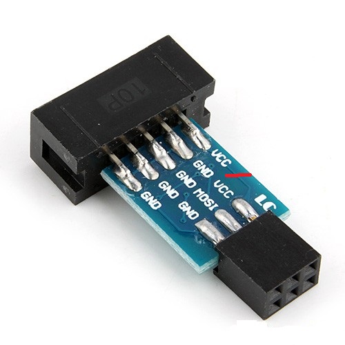
Hardware to use: USBasp avr progarmmer, its on ebay for a couple of $, you will need a 10pin to 6pin adapter to.
Program to download: Arduino IDE 1.0.5-r2 and some librarys and settings for Arduino IDE Arduino files
Place boards.txt & programmers.txt in \arduino-1.0.5-r2\hardware\arduino folder and place the foders rfm22 & TinyGPS in \arduino-1.0.5-r2\libraries foler
Dont forget to restart Arduino IDE to get the changes to take effect.
Open Arduino IDE and navigate to Tools - Board, at the bottom you will see: Tracker Low Power (1.8V, 4 MHz) w/ ATmega328
Open Tools - Programmer and select USBasp
To avoid breaking the GPS chip with to high voltage I recommend to desolder or put a pinhead jumper on the vcc pin on the 10to6 pin head and power the tracker board with it own power source.
(only for MAX6, as the MAX7 and MAX8 gps can handle 1,65-3,6V)
Burn Bootloader by going to: Tools - Burn Bootloader, the bootloder is set with fuses that lets the board run on ext crystal at low power, you can see the fuses in the "boards.txt".
Read more about the fuses in Fuses1 and Fuses2
Thats about it, just load up the "picotracker.ino" code found on Github: ok1cdj/Picotracker , set the frequency and baud in the code and hit "File" - "upload using programmer"
If all goes well it should start compiling and transfer the code to the tracker board, never mind it says something about com 1 or something like that as its an USBasp, its not using com ports, and be
sure you put the 6pin programmer head the right way when you program the board.
There is alot of code besides OK1CDJ code that is compatible with this board, see bottom section of this page.
Note 1! The tracker does not start if it cant "talk" to the gps, a tip is that you fit all components except the gps module and load up this code
CHEAPO it will work without the gps module.
Note 2! There might be an error in original 3,1 schematic regarding the 1,5V - 1,8V converter, its states R6-820Kohm and R8 - 430Kohm,
the correct values should be the other way round R6-430Kohm and R8-820Kohm and that is now corrected on the Github.
I got R6-220Kohm and R8-430Kohm to work as well.
Finaly a BIG thanks To Ondrej - OK1CDJ making this available and maintaining/updating the Github files.
And of course thank to all other great hab sources on Github
---------------------------------------------------------------------------------------------------------------------------------------------
Next is my own  project using readily available modules from ebay, much like these project: Tracker1,
Tracker2,
Tracker3.
project using readily available modules from ebay, much like these project: Tracker1,
Tracker2,
Tracker3.
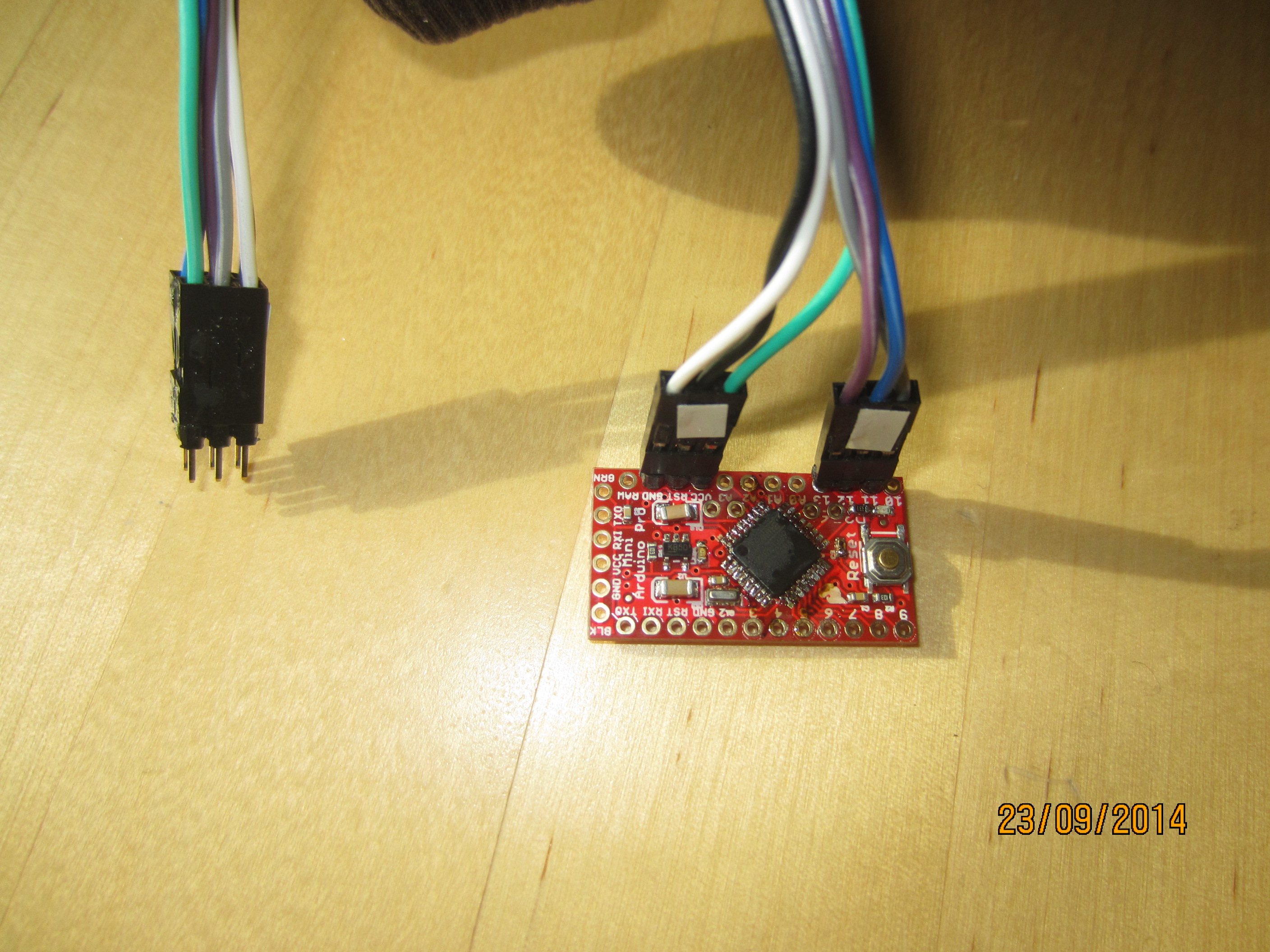
Home made ISP programming cable for arduino pro mini
Update, made one tracker this way but it died, probably to static electricity, it was a pain in the xx to build!!
I abandoned this idea as I found a pcb maker that makes the pcb:s for 1$ a piece, so much easier to build!!
---------------------------------------------------------------------------------------------------------------------------------------------
Here is a pic of the first one built:
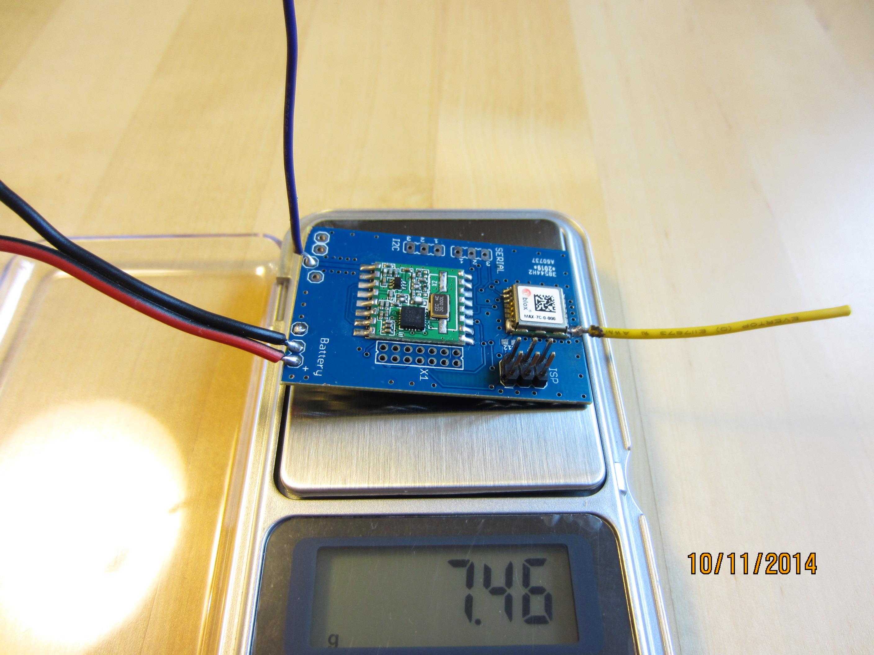
Some modification from the original design made it about 5 grams lighter, first I got the pcb made at 0,8 mm thicknes,
I have also removed the front part where the gps chip antenna used to be located, I also made the gps antenna pad a little bigger
so I could solder a 1/4 wave gps antenna with a lengt of about 45mm.
Pcb maker that I used is Dirty pcbs, it will take about 3 weeks for the pcb:s to arrive.
I got 14 pcb:s for 14$ incl P&P, but it got to be under 5cm lenght, you have to modify the pcb as I did.

Complete tracker with antennas and battery @ 16 Grams
