Equipment
Home


Here you can find information about equipment I use and several tehnical projects.  All equipments have been built together with Robi, S53WW
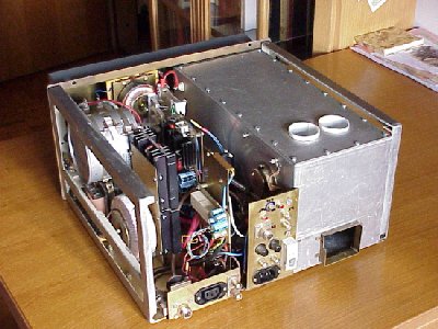
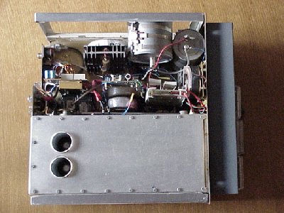
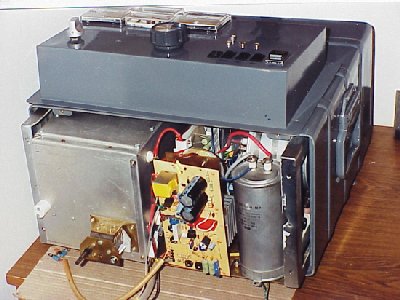
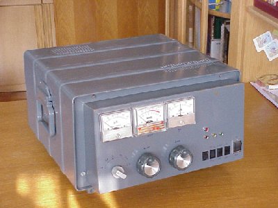
2m PA GS-35b

2m PA 2X4CX300

Kenwood TS-850 modification (XVRT conn)

2m PA GS-35b

gs1.jpg (35806 bytes) gs2.jpg (36824 bytes)
HV Power supply (HV transformer is missing) last testing at home
linear cel.jpg (30005 bytes) linear s strani.jpg (35040 bytes)

GS-35b during operation: up RF part, bellow HV power supply

RF part from side

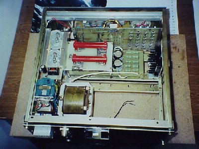
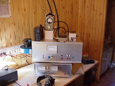
Power amplifier "Vasilij II." with GS-35b is built around former Russian military base station which was used for air-ground communication. We removed all electronics and some mechanical parts except tunable resonator (100-150 MHz), RF output filter, directional power detector and coaxial relays.

All electonic circuits are new. Several protections have been added (Ia, Ig, VSWR).

We added power divider into the RF box so we can put the power in two separate antenna systems (500W in each - we use this configuration for contests).  With appropriate connections all the power can be put in to one antenna system. You can see 11 N-type connectors on the top-rear side.

2m PA 2x3CX300

pa4.jpg (35944 bytes) pa5.jpg (32618 bytes)
inside box from top
pa7.jpg (33193 bytes) pa-2.jpg (26091 bytes)
from front PA (HV transformer is missing on the photo)

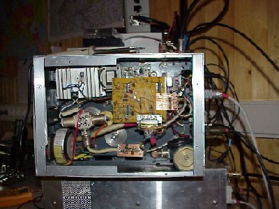
PA was constructed based on YU1AW design in 1995 and 1996 with 4CX250B tubes. Amplifier was working just fine and stable and then one day I forgot to connect the blower. After that output power droped down to about 500 W (tubes became very old, hi). So I decided to replace the tubes. After unsuccessful trial with RE 025XA tubes (Tesla), I replaced them with 4CX300A. Now it delivers about 700 W.
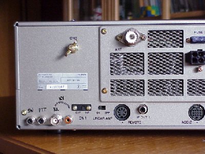
On the left-bottom photo you can see voltage regulator by G3SEK with several protections
against loosing anode voltage, Ia and Ig2 over current.

Toroid HV transformer, blower and fan are not seen on the photos.

TS-850 Modification

ts850.jpg (34601 bytes)

On the photo you can see an easy solution to connect XVRT to TS-850 (separate RX and TX line). Read instructions in Dubus 2/1992 first and decide if that solution is satisfactory for you. If not:

  1. drill 4 (or 3) holes on rear side of transciver for the connectors of your choice (3 RCA and 1 BNC in my case)

  2. RX: cut the coaxial cable that goes from FILTER UNIT to RF UNIT conector CN1 (signal RAT) close to the RF unit (this position should be near the location of new holes). This is receive cable: cable from CN1 (RF UNIT) goes to BCN connector (marked "RX" on photo) and the other end of cable goes to RCA connector (4th connector from left, marked with line to BNC and letters "KV" on photo). If you want to use transciver on HF you have to make link back between those BNC and RCA connectors.

  3. TX: remove the resistor R56 (10k) near the CN25 connector on the RF UNIT (this is only neccessary if you don't have DC blocked IF input in transverter). To redirect TX signal to the IF OUT 1 RCA connector on the rear side of rig, one must apply +12V to the base of Q4 via external 10k resistor. I take this voltage from the ACC1 connector, pin 3 and connect it to the RCA connector marked "SW" on photo.

  4. PTT: you can use REMOTE connector or add additional RCA connector (2nd on photo from left to right).

One very good feature of TS-850 is analog AGC voltage output that can be used as very accurate receive signal strength meter (S-meter). This voltage is available on ACC2, pin 6 and comes from IF UNITas signal SM (signal monitor). When using big meter one can have under 1 dB resolution of RX signal level in 100 dB dynamic range (from -96 dBm to +4 dBm). With proper calibration absolute values of receiving levels can be read. AGC voltage goes from 5.16 V for +4 dBm to 0,22 V for -96 dBm and is fairly linear in the middle region (about 30 mV per dB). With AIP OFF one can get additional 16 dB of RX level measurement sensitivity.

Also the IP3 was checked to see if the band pass filter switching diodes are responsible for 10 dB lower IP3 on 28 MHz with respect to the 14 MHz value (as measured in the ARRL lab). We found no deterioation of IP3 with diodes present - it was around +19 dBm in both cases for 20 kHz signal spacing. The IP3 on 14 MHz was only around +22 dBm for 20 kHz spacing.