LM317 TRANSMITTER
By Harry Lythall SM0VPO
A few years ago I built one of those projects that never worked but it
did do something unusual. The PSU side of a portable receiver was very
unusual as it GENERATED RF in the HF spectrum. The fault was traced to
a couple of errors on the PCB. After a little investigation I used the
error to build myself an HF CW (QRP) transmitter, based upon an LM317T
voltage regulator chip!!!
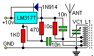
The circuit needs very little explanation. It operates from a 10 volt supply and regulates to about 4.5 volts. This I used to excite the tuned circuit VC1/L1. The tapping is about 3% of the total number of turns of L1. A 6% L1 tap I coupled to the control input if the LM317T regulator chip and BINGO! It "hoots". You can draw WATTS of power from a 12% tapping of L1.
As a STARTING point for VC1/L1, L1 is the usual formula: the number of
turns is the wavelength in meters and the maximum value of VC1 is the
same in pf (multiply by 2 because it is a variable capacitor).
| Coil | Wavelength (in meters) | = | number of turns |
| Capacitor | Wavelength (in meters) | = | Capacitance (pf) X2 |
I see no reason why you cannot use a regulator chip rated at a few amps
to get even more power out. I used this circuit on the air, on 1.8 MHz,
& actually had a few contacts. It will certainly work on the new 70KHz
band, but I do not know how far you can push it into the HF spectrum. I
have just presented notes from my lab-book, & now it is up to those who
wish to experiment a little further.
Have fun, and if you have any major success, such as exceeding 10 watts, then drop me a line and tell me what you did.
Return to Qrp Home Page | QRP Transmitters Page

