Driftcorrection for LC-oscillators |
|
|
![]() here has been written a lot about stabilizing VFO's since
the late Klaas Spaargaren, PAøKSB published his first article on this subject
some 25 years ago. Over the years, many amateurs have copied PAøKSB's method and
in Februari 1996 Klaas published an improved version in ARRL's QEX magazine;
also published in the Dutch magazine "Electron" in December '96.
here has been written a lot about stabilizing VFO's since
the late Klaas Spaargaren, PAøKSB published his first article on this subject
some 25 years ago. Over the years, many amateurs have copied PAøKSB's method and
in Februari 1996 Klaas published an improved version in ARRL's QEX magazine;
also published in the Dutch magazine "Electron" in December '96.
At that
moment I was trying to minimise the drift of the VFO (5-5,5MHz) in my homemade
QRP RTx.
Unfortunately there was no print design available so I made one which is described here. At the end of this page you can find a download link for the schematic, layout plans and a HPGL file for printing your own 1:1 pcb. In short terms I'll explain how the circuit works. Keep in mind, that the circuit itself is not my design, but from Klaas Spaargaren PAøKSB who originated the system in the 1970's.
Why an improved design. Does the old one malfunction? No, but the counter
method used in the first design was to slow and due too modern IC's an
improvement was possible.
|
|
Klaas used a D-flipflop as a digital mixer to downconvert the VFO frequency and a crystal reference signal to a much lower value for further treatment. This signal is than compared with another low value signal and when the VFO drifts away it is regulated to its original frequency by means of a varicap in the VFO until both values are equal again. This method has a significantly better performance than the counter method.
|
|
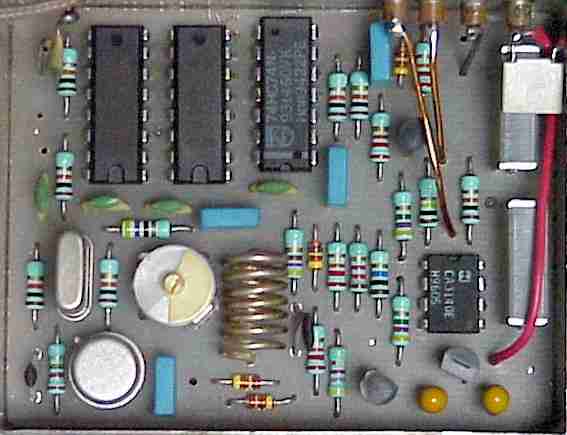
Shown is a practical circuit for the improved system. Two cascaded binary dividers, U1 and U2 divide the VFO frequency by 32768 in 15 cascaded stages. This forms the clock signal for the 74HC74 D-flipflop. The crystal oscillator operates at 48MHz using a 16MHz crystal. Q1 and Q2 (S1 and S2 in the block schematic) are both normally off with an on time determined by the differentiating RC networks in their bases and is less than 1mS per pulse. The output voltage has a range of 0 to 10V. After turn-on it starts in the middle of its range. To reset the circuit press S3 (panel mounted). The varicap tuning must be approximately 1kHz/Volt.
 |
(52 x 67mm) |
 |
Testing the
dividers:
- the amplitude of the VFO signal to the first divider must
be about 4V p-p
- the amplitude of the crystal oscillator must be 4V too
(point 'T') measured with a
multimeter and adjusted by the trimmer. Precise frequency is unimportant.
-
pins 14 and 15 of U2 are LF signals (152Hz and 38Hz when the VFO is
5MHz).
The output will be square waves and a DC voltmeter should
indicate 2,5V. When not
working, the output will be either 0 or 5V.
You can also check with an earphone and
series resistor for sharp
sounding ticks.
Testing the
integrator U4:
- temporarily loosen the 4M7 resistors
- push S3 for
reset
- point V should measure about 5V DC
- connect point 'A' several seconds to 0V. The 10M resistor
will load the 2,2uF
integrator-condensator
- point 'V' should increase 1V every 4,4 second
-
release point 'A' to check the level at
point 'V'. It should not change anymore.
Testing the
comparison circuit Q1 and Q2:
- again loosen the 4M7 resistor from
Q1
- only Q2 is active now and the DC voltage at point 'V' should decrease 1V per 100 sec.
-
resolder the 4M7 resistor.
Last
check:
Slowly move your hand towards the VFO when tuned at a
calibration signal. You should hear the stabilizer correcting the VFO
signal.
Ready!!
Sorry for you, but I don't provide or sell
printed circuit boards.
You can make one yourself by printing a 1:1 copy of
the PCB design. GIF and HPGL formats are included in the ZIP-file below.
|
|
Download Schematic, Component layout, Bill of materials and PCB Files (130Kb) |
|
Huff Puff Stabilizer for the Drake TR7 or TR7A transceiver.
by Rien - PA0TRT |
![]() his circuit is based on the stabilizer by PA0KSB. I have
made some modifications and additions to make the circuit suitable for the Drake
TR7. Read for the full explanation of the stabilizer the original publication in
English QEX Feb. 96 or in Dutch Electron Dec. 96 and Jan. 97
his circuit is based on the stabilizer by PA0KSB. I have
made some modifications and additions to make the circuit suitable for the Drake
TR7. Read for the full explanation of the stabilizer the original publication in
English QEX Feb. 96 or in Dutch Electron Dec. 96 and Jan. 97
Description:
I have
used the 40MHz crystal oscillator that is already built in the TR7 as reference
for the stabilizer circuit. A buffer amplifier BF494 amplifies the signal to a
level high enough to drive the digital mixer 74HC74.
The PTO output (as the VFO is called by Drake) is amplified to drive the binairy counter 74HC4060.
The Drake PTO has already a RIT input line that is connected to a varicap
diode inside the PTO. This same line can also be used for the stabilizer.
The
RIT control line and the output of the integrator CA3140 are added together in
the summing amplifier NE5534 and go the original RIT input of the PTO.
I have added a reset circuit to the original design. When the TR7 is switched on, the output of the integrator is always set to the midrange value of 4V. A manual reset input is also available. When the reset input is made high (+2..+10V) the integrator will also reset to mid range. So far I have not connected this manual reset line, because the total drift was never large enough to reach the limits.
Two comparators LM258 measure the output of the integrator. If the voltage
comes within .5V of the upper or lower limit the LED lights up.
Optional the
output of the comparators can be connected to the reset circuit. However if this
auto reset takes place the PTO will jump from its set frequency. This may not
always be desired.
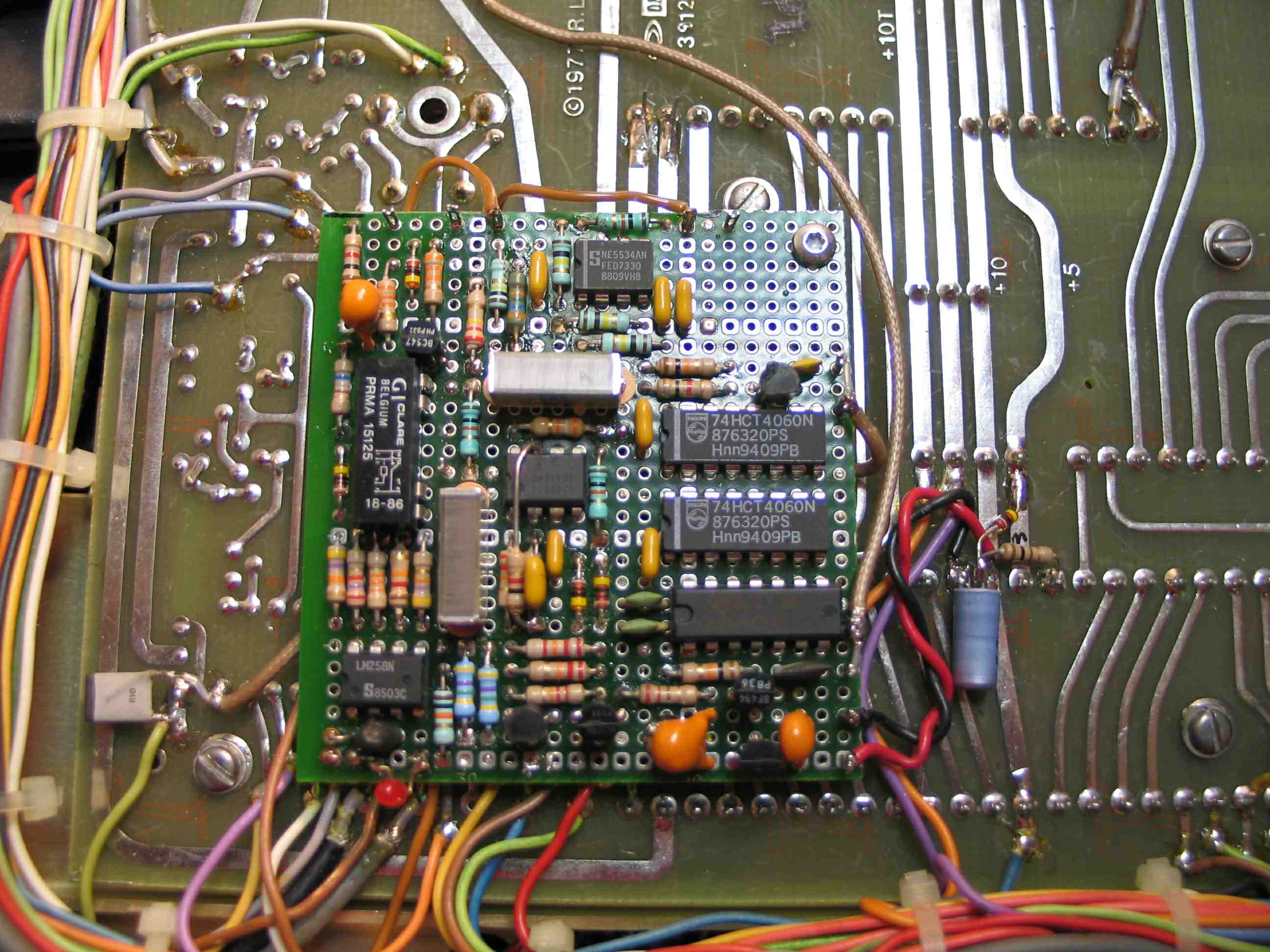
Construction:
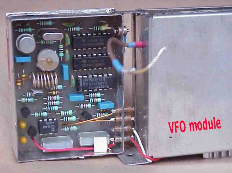
The
stabilizer was constructed on a 75x75 mm piece of perforated experimenter board.
All components are at one side while at the other side all connections were made
with thin bare wire and isolated wrap wire where needed. There is no printed
circuit board available. My layout can be used as a guideline to other
design.
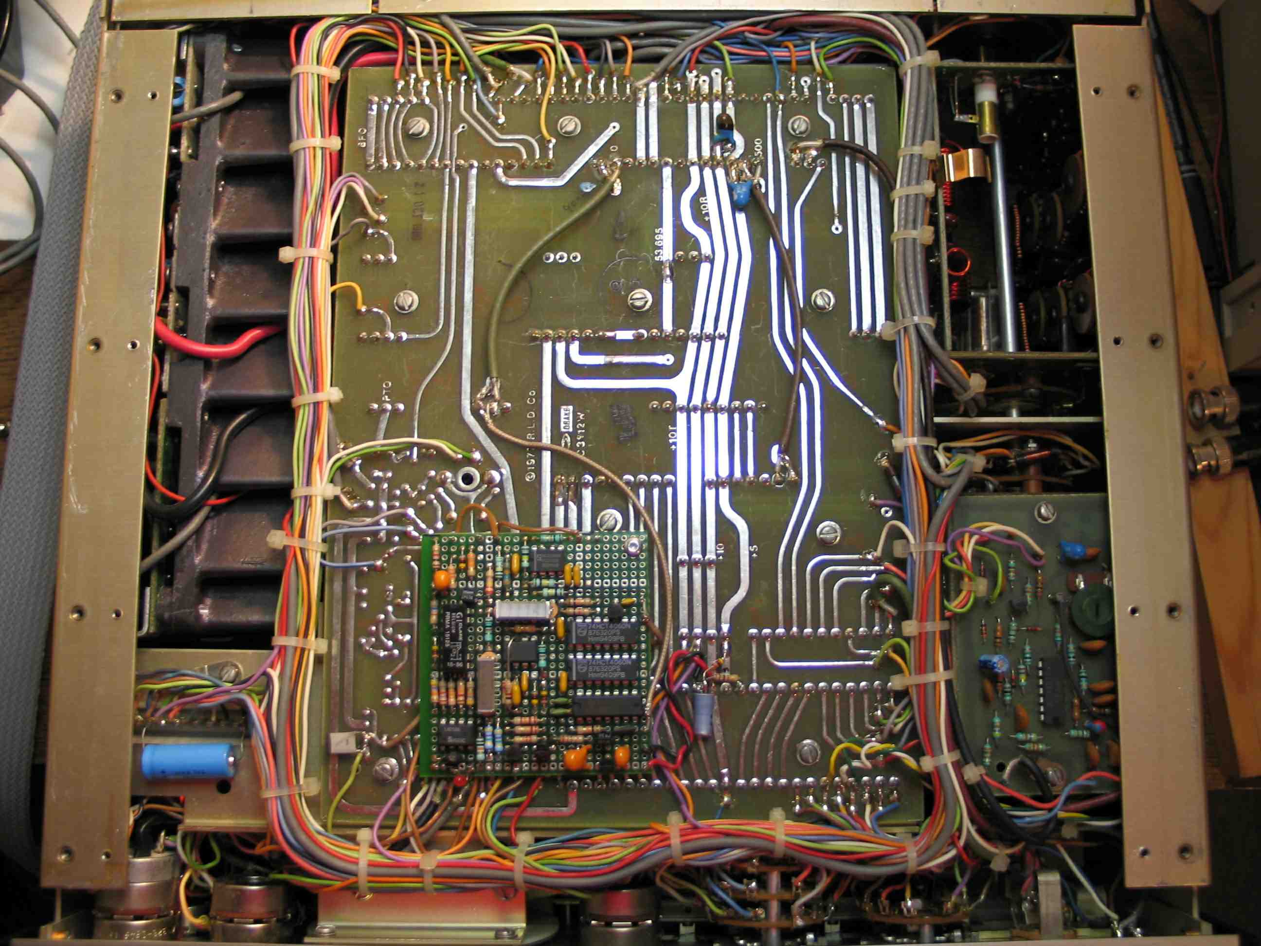
The board is mounted under the parent board of the TR7 (see photos).
At one side the board is mounted with a 5mm spacer, using an existing screw
position in the parent board. The original screw was replaced by a longer one to
hold the board.
At the other side of the board an isolated 5mm stand off
prevents the board from touching the parent board. At the inside of the bottom
cover. I have glued a plastic isolation sheet to prevent the board touching the
bottom cover.
All connections between the TR7 and the stabilizer are directly
to the parent board, only one wire has to be removed from the parent board and
extended to the stabilizer board.
A 100pF capacitor is mounted directly
between the connection point of the PTO to the parent board and the coaxial
cable. This to minimize the capacitive loading of the PTO by the cable.
Adjustment:
After
completion the RIT center position has to be readjusted.
Hold the reset line
high. Exactly center the RIT control on the TR7 front. Switch the calibrator on.
Switch PBT on. Center the PBT control. Switch the RIT on.
Tune the receiver
to exactly zero beat to one of calibrator points. Switch the RIT off. Adjust R24
on the parent board exactly zero to beat. (R24 can be reached through the small
access hole in the parent board just above the stabilizer board on the
photo.)
Results:
Without
the stabilizer my TR7 drifted after switch on over about 500Hz in 5 hours. With
the stabilizer build in, no drift took place. The locking points appear to be
about 20Hz apart.
Rien, PA0TRT
2-2004
|
Click for large screen views.
|
|
|
 |
|
|
Download this text, diagram and component layout for prototyping board (150Kb) |
|
|
Download original publication (PDF) in English QEX Feb. 96 (830Kb) |
References:
-
VERON's magazine Electron (December 1996, p517-521 and January 1997, p10)
-
RadCom's Technical Topics (July; August, p80 and September 1996, p68)
- The
ARRL's QEX (February 1996, p19-23)
- RSGB Handbook 1994
- TR7 Manual