CERAMIC RESONATOR VXO
We show here a different VXO, as it joins the crystal oscillator advantages (stability, performance and easiness of building) with the LC oscillator advantages (versatility and cost). We will speak about a Colpitts VXO with a garden type NPN transistor, in the future we will be able to speak about digital oscillators (running with inverter gates).
The tests done by us show an excellent performance until 4 MHz, very good until 8 MHz and acceptable till 12 MHz, from that frequency we recommend the use of frequency doublers and triplers, based in lower frequency oscillators.
The tests show as possible frequency shifts until 5% downward and 2% over the nominal (printed on the part).
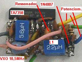
Photo of JABUCA mixer, VXO on the right side
THE CERAMIC RESONATOR
We will not speak here about the way they work and much less of their different applications or ceramic resonator models, we will look at their use in VXO oscillators for hams.
There are a lot of manufacturers and a lot of existing in the market resonators, in some circuits we built the oscillator performance varied a lot in function of the type (or manufacturer) of that resonator, arriving in a lot of cases to not start in the circuit.
A rule that can be applied is the use of two terminal ZTA types, as they are the best choice. The three terminal ZTT type ones have a capacitor connected from each resonator leg to the center pin, so when we use a three terminal resonator (connecting the extreme legs) we will have to think there is a parallel capacitor (usually each capacitor value is 30pF so they result in 15pF in parallel with the resonator), that makes the performance to be affected, but it does not prevent their use.
THE VXO OSCILLATOR
The oscillator circuit is the well known Colpitts. It works with about 8 mA at 8 Volts. It has the output via the emitter that results in a lower output impedance.
The resonant circuit is put between the transistor base and the ground, in our case the series ceramic resonator - inductor - varicap diode circuit.
The feedback that starts the oscillator is done by the capacitive divisor between base emitter and ground (see table as a function of frequency).
The 47KOhms resistor biases the base, which has the voltage limited by the 1000 Ohms (1K) resistor in the emitter. The 1K resistor limits the collector current, too.
The 4.7pF capacitor passes the RF signal to the next stage, blocking the DC current passing.
The inductor and 1N4007 diode, which is an 1 A and reverse voltage of 1000 Volts rectifier diode but it is used here as a varicap diode , leg works as a LC circuit that makes the resonator frequency to lower and covering the desired range. The tuning is done by the potentiometer (any value between 25K and 1M) that adjusts the voltage between 0.1 and 8 Volts, this voltage is filtered by the .1µF capacitor and it feeds the diode via a 100KOhms resistor, the diode capacitance varies with the reverse voltage applied to its terminals (here the capacitance variation is not linear with the voltage). The other potentiometer works like a manual RIT, varying the reception frequency a bit over and under the transmission frequency.
Electronic parts
The 455KHz to 50MHz ceramic resonators can be found easily in the shops here, the use of ceramic resonators replacing the crystal is not much spread in Brazil yet, the resonators have a Q lower than crystals, but a lot higher than that of the equivalent LC circuit, which gives it good stability properties with a wide possible frequency tuning range. The use of them in VXOs shows an optimal stability until 4MHz, a good one till 8MHz and acceptable till 15MHz.
Even without using special capacitors the stability has nothing to owe to that of a crystal, also presenting good immunity to the body capacitance, being possible to build the VXO in the open or without shielding.
When bigger the inductor value, bigger will be the frequency tuning downwards, only limited by unstability surges, a series capacitor also pushes the frequency downwards (the bigger the capacitor the lower the frequency).
The inductor choice must be done through the table.
A trimmer connected in parallel with the varicap diode sets the lowest frequency in the desired range.
The 4.7 pF (4p7) pass capacitor joins the VXO to the buffer (isolating amplifier) this value is low because the need of a weak coupling between the two stages, because with a strong coupling (over 22pF) we had a chirp in the transmission due to buffer load variations.
The 47KOhms potentiometer can be replaced with others with higher values, even 1Mohms.
The resistors must be used as specified and their dissipation value in Watts can be 1/16 W (these are smaller in size) or more Watts.
The transistor can be a 2N3904, 2N2222, BC548B, BC548A, BC547A or BC547B .
|
Banda MHz |
Varicap max |
C1 = C2 |
L1 |
C3 |
Resonator |
|
1,5 - 3 |
130pF |
470pF |
100µH |
33pF |
2 - 2,46 |
|
3 - 5 |
65pF |
220pF |
47µH |
18pF |
3,14 - 3,45 - 3,64 - 3,68 - 3,84 - 4 |
|
5 - 9 |
32pF |
100pF |
5,6µH |
6,8pF |
5 - 6 - 7,15 - 8 |
|
9 - 12 |
20pF |
100pF |
2,2µH |
4,7pF |
10 - 10,7 - 11 - 11,06 - 12 |
|
12 - 15 |
16pF |
100pF |
1,8µH |
4,pF |
13,56 - 14,32 |
Table with parts values, these values can be changed and were tested in built VXOs.
Construction
For the board layout we usually number the islands in order to ease the layout making and the construction.
This board must be fixed (soldered) with rigid wires in another base board, serving as a base for the rest of the rig.
Tests
1.Before powering check there are no short circuit connections due to solder excess.
2.Check if all has been soldered suitably.
3.Check the transistor pins are well connected.
If you have a receiver able to tune the VXO frequency or its multiples try to hear the VXO signal.
Connect the power terminals in a 7.5 to 15 Volts direct current (DC) power supply to the Negative and Positive terminals.
If you have a multimeter it is advisable to connect it to measure the current consumption and to protect the circuit/power supply from a possible short-circuit. If you do not have one, skip this part.
"Put the multimeter in the appropriate scale to measure 20 or 30 mA (DCmA), connect the + multimeter probe to the power supply positive terminal and the - probe (common) to the positive of our VXO. The negative power supply terminal is connected directly to the VXO negative.
When switching the power on if all is correct we will have a consumption between 5 and 10mA, pending on the power voltage. Bigger currents are signals of problems. If the multimeter show a minus reading you have to invert the + and - probes, if the reading is to end of scale switch off the power immediately, we have a short circuit or the transistor is mounted with inverted terminals. Correct the problems till getting the result described above."
Connect our VXO power terminals to that of the power supply making sure about the polarities.
Put a LED diode between our output wire and the ground terminal and the Led must light on.
Another tests could be done building an RF voltmeter with 4 parts and using it with the multimeter. That circuit is described in other part in our homepage.
Adjustments
The trimmer must be adjusted in order to set the lowest desired frequency, with the tuning potentiometer set to the power supply negative side, if you do not get the desired band covering even adjusting the capacitor value, the RF choke will have to be replaced by one with higher value (or another in series with the one existing). A new value for the capacitor will have to be found. Repeat these operations if necessary.
Use in other VXO types
The use in other VXO using ICs like the NE/SA612 or NE/SA602 or TA7358 is possible, respecting the table values, leaving out the C3 capacitor that will not be necessary in these cases.
The use in digital VXOs with inverter gates is possible, this topic will be explained in the digital transmitters description, in the transmitter area of this homepage.
VXO A RESSONADOR CERÂMICO
Apresentamos aqui um VXO diferente, pois reúne as vantagens de um oscilador a cristal (estabilidade, desempenho e facilidade de montagem) com as vantagens de um oscilador a LC (versatilidade e custo). Falaremos sobre um VXO a transistor NPN de uso geral, tipo Colpits, futuramente poderemos falar sobre os osciladores digitais (funcionando com portas inversoras)
Os testes por nós realizados apresentam uma performance excelente até 4 MHz, ótima até 8 MHz e aceitável até 12 MHz, a partir deste ponto recomendamos o uso de dobradores e triplicadores de freqüência, baseados em osciladores de até 4MHz.
Os testes mostram como possíveis desvios de freqüência de até 5 % abaixo e 2 % acima da nominal (estampada no componente).
Foto mixer do JABUCA, VXO a direita
O RESSONADOR CERÂMICO
Não falaremos aqui de como funcionam e muito menos das diversas aplicações ou modelos dos ressonadores cerâmicos, nos deteremos a aplicação deles em osciladores VXO para radioamadores.
São muitos os fabricantes e muitos os modelos de ressonadores existentes no mercado, em alguns circuitos que montamos o desempenho do oscilador variava muito em função do tipo (ou fabricante) do ressonador, chegando em muitos casos a não oscilarem no circuito.
Uma regra que pode ser aplicada é o uso de tipos como o ZTA de dois terminais, o que é a melhor escolha. Os do tipo ZTT de três terminais, possuem um capacitor ligado a cada extremidade do ressonador ao centro, assim ao utilizarmos um ressonador com três terminais (ligando as extremidades) teremos que considerar que existe um capacitor em paralelo (normalmente o valor de cada capacitor é de 30pF o que resulta em 15 pF em paralelo com o ressonador), isso faz com que o desempenho seja afetado, mas não impede seu uso.
O OSCILADOR do VXO
O circuito oscilador é o conhecido Colpits. Trabalha com cerca de 8 mA em 8 Volts. Possui a saída via emissor que resulta em uma impedância menor de saída. .
O circuito ressonante é colocado entre a base do transistor e o terra, em nosso caso a série ressonador cerâmico - indutor - diodo de capacitância variável.
A realimentação para o circuito oscilar é feita pelo divisor capacitivo entre base emissor e terra (ver tabela em função da freqüência)
O resistor de 47kOhms polariza a base, que tem tensão limitada pelo resistor de 1000 Ohms (1k) no emissor. O resistor de 1k limita também a corrente de coletor.
O capacitor de 4,7pF acopla sinal de RF do oscilador ao estagio seguinte, bloqueando a passagem de corrente continua.
O conjunto indutor e o diodo 1N4007, que é na realidade um diodo retificador de 1 A e tensão inversa de 700 Volts mas aqui é empregado como diodo varicap, compõem-se em um circuito LC que faz a freqüência do ressonador abaixar e cobrir a banda desejada. A sintonia é feita pelo potenciômetro (valor entre 25k a 1M) que ajusta a tensão entre 0,1 a 8 Volts, esta tensão é filtrada pelo capacitor de .1µF e é alimenta o diodo via um resistor de 4 100 kOhms, a capacitância do diodo empregado varia com a tensão aplicada inversamente nos seus terminais (aqui a variação de capacitância não é linear com a tensão). O outro potenciômetro atua como um RIT manual, variando a freqüência na recepção um pouco acima e abaixo da freqüência de transmissão.
Componentes
O ressonadores cerâmicos de 455kHz a 50MHz podem ser encontrados com facilidade no comércio, o uso de ressonadores em substituição ao cristal ainda é pouco difundido no Brasil, os ressonadores tem um Q menor que o cristal, mas muito superior a um circuito LC equivalente, o que lhe confere as propriedades de boa estabilidade de freqüência com uma ótima possibilidade de variação. O uso em VXOs apresenta ótima estabilidade até 4MHz, boa até 8MHz e aceitável até 15MHz
Mesmo sem a utilização de capacitores especiais a estabilidade não deixa nada a dever para o cristal, alem de apresentar uma imunidade à capacitância do corpo, sendo possível montar o VXO em local aberto ou sem blindagem.
Com o valor do indutor maior, maior será a variação da freqüência para baixo, limitada ao surgimento de uma instabilidade, um capacitor em série também "puxa" a freqüência para baixo (maior valor do capacitor menor a freqüência).
A escolha do indutor deve ser através da tabela.
Um trimmer ligado em paralelo com o varicap determina a menor freqüência da faixa desejada .
O capacitor de acoplamento de 4,7 pF (4p7) acopla o VXO ao buffer (amplificador acoplador) este valor é baixo devido a necessidade de um acoplamento "frouxo" entre os dois estágios, pois com um acoplamento forte (acima de 22pF) teríamos um piado na transmissão devido a variação de carga do buffer.
O potenciômetro de 47kOhms pode ser substituído por valores até de 1MOhms .
Os resistores devem ser utilizados conforme especificado e o valor em Watts de dissipação pode ser de 1/16 W (estes são menores em tamanho) ou mais Watts.
O transistor pode ser o 2N3904, 2N2222, BC548B, BC548A, BC547A ou BC547B .
|
Banda MHz |
Varicap max |
C1 = C2 |
L1 |
C3 |
Ressonador |
|
1,5 - 3 |
130pF |
470pF |
100µH |
33pF |
2 - 2,46 |
|
3 - 5 |
65pF |
220pF |
47µH |
18pF |
3,14 - 3,45 - 3,64 - 3,68 - 3,84 - 4 |
|
5 - 9 |
32pF |
100pF |
5,6µH |
6,8pF |
5 - 6 - 7,15 - 8 |
|
9 - 12 |
20pF |
100pF |
2,2µH |
4,7pF |
10 - 10,7 - 11 - 11,06 - 12 |
|
12 - 15 |
16pF |
100pF |
1,8µH |
4,pF |
13,56 - 14,32 |
Tabela com valores dos componentes, estes valores podem variar e foram testados em VXOs montados
Montagem
Para confecção do layout de placa costumamos numerar as "ilhas" para facilitar a elaboração (do layout) e para a montagem
Esta placa deve ser fixada (soldada), por fios rígidos, em outra placa de base. Que servirá de base para o restante da montagem.
Testes :
1.Antes de ligar verifique se não há ligações com curto circuito devido a excesso de solda.
2.Verifique se tudo foi soldado adequadamente.
3.Verique se os lides do transistor estão ligados corretamente.
Caso você tenha um receptor da freqüência do VXO ou de múltiplos dela procure ouvir o sinal do VXO.
Ligue os terminais em uma fonte de alimentação de 7,5 a 15 Volts corrente continua (DC) aos terminais Negativo e Positivo.
Caso você tiver um multímetro é aconselhável conecta-lo para medirmos o consumo de corrente e proteger o circuito/fonte de um possível curto-circuito. Caso não tenha pule esta parte.
"Coloque o multímetro na escala para medir 20 ou 30 mA (DCmA) conecte a ponta + do multímetro no terminal positivo da fonte e o terminal - (comum) no positivo do nosso VXO. O terminal negativo da fonte vai diretamente conectado ao negativo do VXO.
Ao ligar a fonte se tiver tudo certo teremos um consumo entre 5 e 10mA, dependendo da tensão da fonte. Correntes maiores são sinais de problemas, caso o multímetro indique para menos você inverteu as pontas + com - , caso a leitura seja fim de escala DESLIGUE IMEDIATAMENTE temos um curto-circuito ou o transistor esta com os terminais invertidos. Corrija os problemas até obter o acima descrito."
Ligue os terminais do nosso VXO aos da fonte de alimentação certificando-se das polaridades.
Coloque um diodo Led entre o nosso fio de saída e o terminal terra o Led deverá se acender.
Outros testes poderão ser feitos construindo um voltímetro de RF com 4 componentes e utilizado em conjunto com o multímetro. Este aparelho esta descrito em outra parte de nossa homepage.
Ajustes
O trimmer deve ser ajustado afim de regular a menor freqüência desejada, com o potenciômetro de ajuste de freqüência ajustado para o lado negativo da fonte, caso não se consiga uma cobertura da faixa desejada, mesmo ajustando o valor do capacitor, o choque de RF poderá ser substituído por um de valor superior (ou outro colocado em serie). Um novo valor para o capacitor deverá ser encontrado. Repetir estas operações se necessário for.
Uso em outros tipos de VXOs
O uso em outros VXOs em conjunto com Cis. como o NE/SA612 ou NE/SA602 ou TA7358é possível, respeitando os valores de tabela, despreze apenas o capacitor C3 que nestes casos não será necessário.
Já a utilização em VXOs digitais com portas inversoras é possível, este tópico será esclarecido na descrição dos transmissores digitais, na área de transmissores desta homepage.