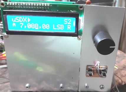
µSDX
com ARDUINO NANO
Este radio eu comecei a montar quando o Guido PE1NNZ fez a
primeira modificação no QCX.
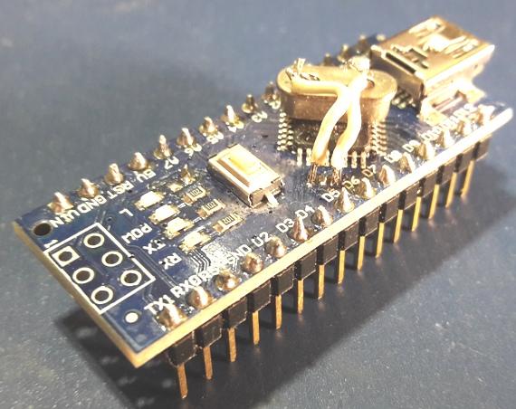
A montagem esta muito congestionada pois optei por usar jumpers.
Apos a modificação do receptor para digital, na nova
versão da modificação, onde surgiu o µSDX,
eu resolvi montar com o arduino Nano, pois devido a pandemia (2020)
não estava facil adquirir componentes.
Eu não tinha o Atmega 328 e nem o 74ACT00.
Eu apanhei (sofri) muito como o upload do software, que na verdade era
muito facil.
Escrevi muitas vezes ao Guido (no grupo https://groups.io/g/ucx ) que
sempre respondeu prontamente.
Montei o receptor que funcionou bem : video
Acabei conseguindo os componentes e montando tambem com o Atmega328PU,
que se mostrou ser bem mais facil de montar.
Mas voltando ao arduino nano.
This radio I started to assemble when
Guido PE1NNZ made the first modification in QCX.
The assembly is very congested
because I chose to use jumpers.
After modifying the receiver to
digital, in the new version of the modification, where µSDX
appeared, I decided to mount it with the Arduino Nano, because due to
the pandemic (2020) it was not easy to acquire components.
I didn't have the Atmega 328 or the
74ACT00.
I got (suffered) a lot like uploading
the software, which was actually very easy.
I wrote many times to Guido (in the
group https://groups.io/g/ucx)
who always responded promptly.
I set up the receiver that worked
well: video
I ended up getting the components and
assembling also with the Atmega328PU, which proved to be much easier to
assemble.
But back to the arduino nano.
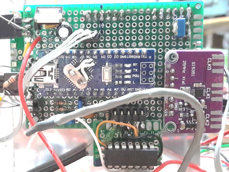
Foto
: o 74act00, o modulo SI5351, o LCD e o arduino nano são
montados com soquete
Photo: the 74act00, the SI5351 module, the LCD and the nano arduino are
mounted with socket
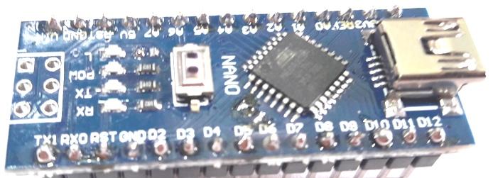
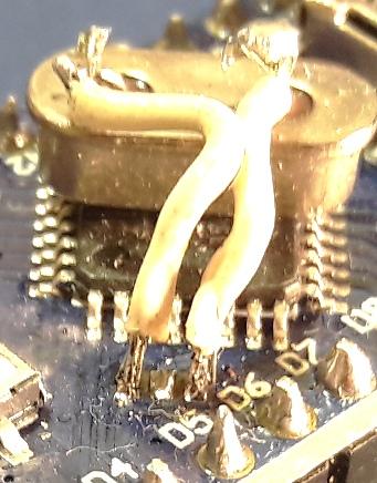
Primeiro retirei o cristal do nano.
Dica : para saber se o novo cristal funciona, antes de retirar o
cristal de 16MHz carregue o sketch "blink" que esta na area de exemplos
da IDE. Verifique se o led na placa pisca. Se OK pode retirar o cristal
com cuidado. Já sem o cristal coloque o novo cristal de 20MHz
provisoriamente (sem soldar) nos terminais onde estava o cristal
original
(são as ligações das pontas, o meio é
terra) faça isto com a arduino ligado...caso o led pisque o
cristal esta oscilando OK. (note que o novo cristal pisca mais rapido
!).
First I removed the crystal from the
nano.
Tip: to find out if the new crystal
works, before removing the 16MHz crystal, load the "blink" sketch in
the IDE's sample area. Check that the led on the board flashes. If OK
you can remove the crystal carefully. Already without the crystal,
place the new 20MHz crystal temporarily (without soldering) in the
terminals where the original crystal was (they are the connections of
the tips, the middle is earth) do this with the arduino on ... if the
led flashes the crystal is oscillating OK. (note that the new crystal
flashes faster!).
Agora solde o cristal no devido lugar e teste ... se OK
Now solder the crystal in place and
test ... if OK
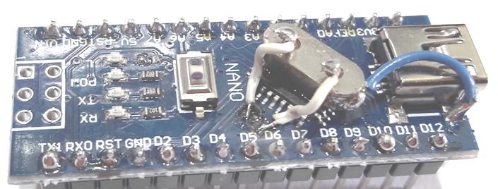
Remova o
resistor que esta ligado ao led que piscava (o resistor esta ao lado do
led "L", proximo ao pino A7). Com o led ligado este pino
não atua corretamente no µSDX !
Remove the resistor that is connected
to the flashing led (the resistor is next to the "L" led, next to pin
A7). With the led on, this pin does not act correctly on the µSDX!
Como carregar o sketch no arduino nano:
Tente carregar diretamente, deve funcionar.
Caso tenha problemas, use outro arduino nano ou arduino uno
ligado e funcionando como "arduino as ISP".
Como fazer o arduino ISP (voce deverá ter outro nano ou um UNO) :
1. Use a IDE1.8.9 do Arduino.
2. Carregue, no
nanoISP ou no UNO ISP,o
programa arduino ISP que esta nos exemplos
(Arquivos>exemplos>ArduinoISP)
3. Com o nano20MHz em um protboard
A. interligue o 5V com 5V e o terra (GND) como terra (GND) do
NanoISP/ UNO ISP ao nano20MHz
B.
NanoISP/ UNO ISP pino 13 ao 13 do nano20MHz
C. NanoISP/
UNO ISP pino 12 ao 12 do nano20MHz
D. NanoISP/
UNO ISP pino 11 ao 11 do nano20MHz
E. NanoISP/
UNO ISP pino 10 ao pino RST do nano20MHz
F. Ligar um resistor de 10K entre o RST e o 5V do nano20MHz.
4. Em Menu>Ferramentas> selecione a placa "arduino genuino uno"
e como programador "Arduino as ISP"
5. Ligue o nano / uno ao PC
6. Abra o arquivo INO a ser instalado no nano20MHz
6. Em Menu>Sketch> selecione "carregar usando programador"
7. OK
How to load the sketch on the arduino
nano:
Try charging directly, it should work.
If you have problems, use another
arduino nano or arduino uno connected and functioning as "arduino as
ISP".
How to make the arduino ISP (you must
have another nano or a UNO):
1. Use the Arduino IDE1.8.9.
2. Load, on nanoISP or UNO ISP, the
Arduino ISP program that is in the examples (Files> examples>
ArduinoISP)
3. With nano20MHz on a protboard
A. connect the 5V with 5V and the
ground (GND) as ground (GND) of the NanoISP / UNO ISP to the nano20MHz
B. NanoISP / UNO ISP pin 13 to 13 of
the nano20MHz
C. NanoISP / UNO ISP pin 12 to 12 of
nano20MHz
D. NanoISP / UNO ISP pin 11 to 11 of
nano20MHz
E. NanoISP / UNO ISP pin 10 to
nano20MHz RST pin
F. Connect a 10K resistor between the
RST and the 5V of the nano20MHz.
4. In Menu> Tools> select the
board "arduino genuino uno" and as programmer "Arduino as ISP"
5. Connect the nano / uno to the PC
6. Open the INO file to be installed
on nano20MHz
6. In Menu> Sketch> select
"load using programmer"
7. OK
Esquema 1 :
Primeiro montei este do esquema funcionou bem.
Depois com fiz algumas modificações que facilitaram a
montagem.
Veja no esquema :
First I set up this scheme worked
well.
Then I made some changes that
facilitated the assembly.
See in the diagram :
A modificação principal foi no amplificador de audio.
Teremos mais modificações ?
Certamente, estamos para retirar o 2N7000 entre o 74ACT00 e o PA, pois
o novo software na versão "M" corrigiu o problema da portadora
sem modulação.
A Modificação consiste em retrirar o mosfet e interligar
as 3 conexões.
Esta modificação dará um pouco mais de potencia ao
µSDX.
Outra modificação é incluir um BPF (filtro passa
banda) e um amplificador de RF, para melhorar a recepçaõ.
Eu resolvi montar o modulo SI5351 (Adafrit ou chines) plugado na placa
e fiz uma alimentação de tal forma que este modulo possa
ser substituido por um modulo caseiro.
L4, C30 e o LPF tambem foram montados em modulo, assim podemos mudar de
banda manualmente.
The main modification was the audio
amplifier.
Will we have more modifications?
Certainly, we are about to remove the
2N7000 between the 74ACT00 and the PA, as the new software in the "M"
version corrected the carrier problem without modulation.
The Modification consists of
retracting the mosfet and connecting the 3 connections.
This modification will give the
µSDX a little more power.
Another modification is to include a
BPF (bandpass filter) and an RF amplifier, to improve reception.
I decided to assemble the SI5351
module (Adafrit or Chinese) plugged into the board and made a supply in
such a way that this module can be replaced by a homemade module.
L4, C30 and LPF were also assembled
in a module, so we can change bands manually.
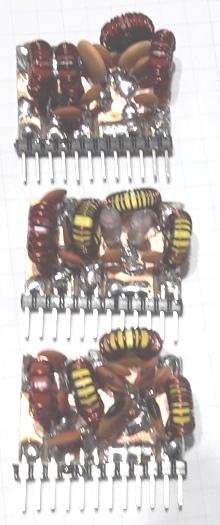
Foto : filtros montados e placa do modulo.
Photo: mounted filters and module
plate.
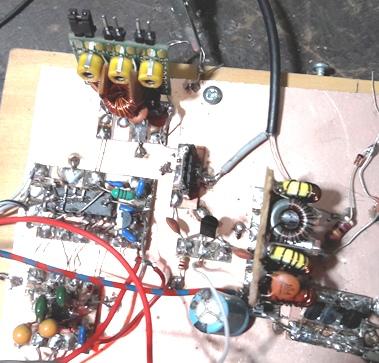
Foto : a esquerda 74hc4053 e NE5532 (receptor) acima fitro passa banda
(em teste), a direita LPF e PA.
Photo: the left 74hc4053 and NE5532
(receiver) above the band pass (in test), the right LPF and PA.
Os valores dos indutores para a montagem
(como esta no esquema) estão neste
link
Um filtro LPF mais simples e muito eficiente foi desenvolvido
pelo Manuel DL2MAN, que utiliza apenas 2 toroides Amidon. Montei o de
40m e funcionou muito bem, a descrição dele esta
aqui (NOTA L1 = 50µH toroide FT37-43 demais T37-6 capacitores C0G
ou NP0 ou micaprateada) :
The values of the inductors for the
assembly (as shown in the diagram) are on this
link
A simpler and more efficient LPF
filter was developed by Manuel DL2MAN, which uses only 2 Amidon
toroids. I mounted the 40m and it worked very well, its description is
here (NOTE L1 = 50µH toroid FT37-43 too T37-6 capacitors C0G or
NP0 or mica silver):
Hi,
The Chebycheff Times are long over ;) This was the parallel resonance
era (vulgo Ghetto) and is no longer Valid.
The answer is simple:
Just use that Spreadsheet:
http://www.wa0itp.com/class%20e%20design.html
While 17m might still work with decent efficieny, I could not make this
work higher up.
Yes, it would create Power, Yes it would work, but efficiency was
around 60% at best for 10m Band....
And
to save you all some Time, I´ve already calculated all the Values
for
3x BS170, 13,8V Input Voltage and 5W desired Output.
...
| 3x BS170
(theoretical) |
|
|
|
|
|
|
|
|
|
| Band |
80m |
60m |
40m |
30m |
20m |
17m |
15m |
12m |
10m |
6m |
| F (MHz) |
3,56 |
5,35 |
7,05 |
10,1 |
14,05 |
18,08 |
21,05 |
24,9 |
28,05 |
50,09 |
| Load (Ohm) |
12 |
12 |
12 |
12 |
12 |
12 |
12 |
12 |
12 |
12 |
| C1 (pF) |
657 |
420 |
307 |
199 |
128 |
88 |
69 |
50 |
39 |
0 (-1) |
| C2 (pF) |
1864 |
1240 |
941 |
657 |
472 |
367 |
315 |
266 |
237 |
132 |
| L2 (µH) |
2,04 |
1,36 |
1,03 |
0,72 |
0,52 |
0,4 |
0,35 |
0,29 |
0,26 |
0,15 |
| C3 (pF) |
1826 |
1215 |
922 |
644 |
463 |
360 |
309 |
261 |
232 |
130 |
| C5 (pF) |
1826 |
1215 |
922 |
644 |
463 |
360 |
309 |
261 |
232 |
130 |
| L3 (µH) |
0,82 |
0,55 |
0,41 |
0,29 |
0,21 |
0,16 |
0,14 |
0,12 |
0,1 |
0,06 |
| C4 (pF) |
609 |
405 |
307 |
215 |
154 |
120 |
103 |
87 |
77 |
43 |
73 Manuel; DL2MAN
xxxxxxxxxxxxxxxxxxxxxxxxxxxxxxxxxxxxxxxxxxxxxxxxxxxxxxxxxxxxxxxxxxxxxxxxxxxxxxxxxxxxxxxxxx
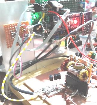
Foto:
PA e LPF
Tentei
usar o Arduino mais simples, mas ele não tem disponivel o
pino Aref, que é muito importante no funcionamento do µSDX
e não foi possivel !
Fiz diversos QSOs com este radio em 40 e em 80m, a
recepção melhorou muito é só conferir no
youtube ..
https://www.youtube.com/watch?v=GSqUwlqWt38
I tried to use the simplest Arduino,
but Aref pin it is not available, which is very
important in the operation of µSDX and was not possible!
I did several QSOs with this radio in
40 and 80m, the reception has improved a lot just check on youtube ..
https://www.youtube.com/watch?v=GSqUwlqWt38
73 de py2ohh miguel
nov/2020