TTL QRPp
Kidding with TTL
Hello friends, here some experiments with TTL, I have a lot of TTLs in my surplus box, and I was just kidding ...
Some of these circuits are difficult to start oscillating and it needs adjustment in the components values.
Remember that 74xx / 74Sxx / 74LSxx / 74ALSxx / 74Fxx are TTL.
All others types who has almost "C" in the name are CMOS and the work impedance are different, do not try to build with IC CMOS using this schematics, the resistors are higher than showed.
All RF measurements are made with a simple germanium diode adapter to a digital voltmeter, the diode junction 0.5V did not added. Bypassed with 100nF ceramic capacitor.
To give a sinus wave you need to add a LPF in the output.
74LS00 4 - NAND gates

Point 1
No load, open output ... 1.6Vp of RF
Loaded with 50R ...0.87Vp of RF
Point 2
No load, open output .... 2.4Vp of RF
Loaded with 50R ...1.41Vp of RF
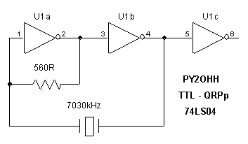
74LS04 6 inverting gates

At pin 6
No load, open output .... 2.0Vp of RF
Loaded with 50R ...0.87Vp of RF
Loaded with 100R ...1.1Vp of RF
In order to give more power, put the others 3 gates in paralell with U1c.
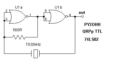
74LS02 4 NOR gates

At pin 4
No load, open output .... 2.0Vp of RF
Loaded with 50R ...0.92Vp of RF
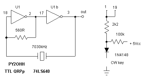
74LS640 Octal Inverting Bus Transceiver Tri-State.

Pin Type Pin number
A 2 ...... 9
B 18 ..... 11
Pin 1 Pin 19 directions
L .............. L ....... Bè A
L .............. L ....... Aè B
L .............. x ....... none
At pin 3
No load, open output .... 2.2Vp of RF
Loaded with 50R ...1.3Vp of RF
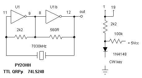
74LS240 Octal Inverting Buffers and Line Drivers.

At pin 12
No load, open output .... 2.4Vp of RF
Loaded with 50R ...1.1Vp of RF
Next steps :