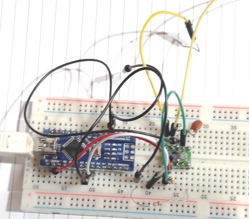
ARDUINO
NANO + SI5351 QUADRATURE or 90 DEGREES PHASE SHIFT (UPDATE jun 2018)
For SDR use : direct from SI5351, dont need 4x, dont need 74xx74.
ATENÇÃO :
a variavel evendivisor não pode ser maior que 127 LINK :
http://qrp-labs.com/images/news/dayton2018/fdim2018.pdf
Lendo informações sobre como gerar uma frequencia com
duas saidas defasadas em 90 graus, deparei com um pequeno sketch
com instruções de como fazer isto com o SI5351 junto com
o arduino, estavam com a excelente biblioteca do colega Jason
Milldrum.
As explicações são claras :
/*
*
si5351_phase.ino - Example for setting phase with Si5351Arduino library
*
*
Copyright (C) 2015 - 2016 Jason Milldrum <[email protected]>
*
* This
program is free software: you can redistribute it and/or modify
* it under
the terms of the GNU General Public License as published by
* the Free
Software Foundation, either version 3 of the License, or
* (at your
option) any later version.
*
* This
program is distributed in the hope that it will be useful,
* but
WITHOUT ANY WARRANTY; without even the implied warranty of
*
MERCHANTABILITY or FITNESS FOR A PARTICULAR PURPOSE. See the
* GNU
General Public License for more details.
*
* You
should have received a copy of the GNU General Public License
* along
with this program. If not, see
<http://www.gnu.org/licenses/>.
*/
/*
* Setting
the phase of a clock requires that you manually set the PLL and
* take the
PLL frequency into account when calculation the value to place
* in the
phase register. As shown on page 10 of Silicon Labs Application
* Note 619
(AN619), the phase register is a 7-bit register, where a bit
*
represents a phase difference of 1/4 the PLL period. Therefore, the best
* way to
get an accurate phase setting is to make the PLL an even multiple
* of the
clock frequency, depending on what phase you need.
*
* If you
need a 90 degree phase shift (as in many RF applications), then
* it is
quite easy to determine your parameters. Pick a PLL frequency that
* is an
even multiple of your clock frequency (remember that the PLL needs
* to be in
the range of 600 to 900 MHz). Then to set a 90 degree phase shift,
* you
simply enter that multiple into the phase register. Remember when
* setting
multiple outputs to be phase-related to each other, they each need
* to be
referenced to the same PLL.
*/
#include
"si5351.h"
#include "Wire.h"
Si5351 si5351;
void setup()
{
// Start
serial and initialize the Si5351
Serial.begin(57600);
si5351.init(SI5351_CRYSTAL_LOAD_8PF, 0, 0);
// We
will output 14.1 MHz on CLK0 and CLK1.
// A PLLA
frequency of 705 MHz was chosen to give an even
//
divisor by 14.1 MHz.
unsigned
long long freq = 1410000000ULL;
unsigned
long long pll_freq = 70500000000ULL;
// Set
CLK0 and CLK1 to use PLLA as the MS source.
// This
is not explicitly necessary in v2 of this library,
// as
these are already the default assignments.
//
si5351.set_ms_source(SI5351_CLK0, SI5351_PLLA);
//
si5351.set_ms_source(SI5351_CLK1, SI5351_PLLA);
// Set
CLK0 and CLK1 to output 14.1 MHz with a fixed PLL frequency
si5351.set_freq_manual(freq, pll_freq, SI5351_CLK0);
si5351.set_freq_manual(freq, pll_freq, SI5351_CLK1);
// Now we
can set CLK1 to have a 90 deg phase shift by entering
// 50 in
the CLK1 phase register, since the ratio of the PLL to
// the
clock frequency is 50.
si5351.set_phase(SI5351_CLK0, 0);
si5351.set_phase(SI5351_CLK1, 50);
// We
need to reset the PLL before they will be in phase alignment
si5351.pll_reset(SI5351_PLLA);
// Query
a status update and wait a bit to let the Si5351 populate the
// status
flags correctly.
si5351.update_status();
delay(500);
}
void loop()
{
// Read
the Status Register and print it every 10 seconds
si5351.update_status();
Serial.print("SYS_INIT: ");
Serial.print(si5351.dev_status.SYS_INIT);
Serial.print(" LOL_A: ");
Serial.print(si5351.dev_status.LOL_A);
Serial.print(" LOL_B: ");
Serial.print(si5351.dev_status.LOL_B);
Serial.print(" LOS: ");
Serial.print(si5351.dev_status.LOS);
Serial.print(" REVID: ");
Serial.println(si5351.dev_status.REVID);
delay(10000);
}
Parti para fazer um sketch que funcionasse e funcionou !
Aqui vai uma forma simplificada de gerar as duas saidas em
quadratura, gera 7000kHz em quadratura nos pinos 9 e 10 durante 10
segundos depois, exemplificando como ajustar a frequencia externamente,
a frequencia vai para 7020kHz já no pino 6 a
frequencia estará em 14050kHz :
Sketch :
#include "si5351.h"
#include "Wire.h"
Si5351 si5351;
volatile uint32_t freqini = 700000000ULL / SI5351_FREQ_MULT;
volatile unsigned long freqini3 = 14050000;
int evendivisor = 100;
void setup() {
si5351.set_correction(100);
si5351.init(SI5351_CRYSTAL_LOAD_8PF, 27000000, 0); // para xtal de 27MHz
//si5351.init(SI5351_CRYSTAL_LOAD_8PF, 0, 0); // este para xtal de 25MHz
si5351.set_freq_manual(freqini * SI5351_FREQ_MULT, evendivisor *
freqini * SI5351_FREQ_MULT, SI5351_CLK0);
si5351.set_freq_manual(freqini * SI5351_FREQ_MULT, evendivisor *
freqini * SI5351_FREQ_MULT, SI5351_CLK1);
si5351.set_phase(SI5351_CLK0, 0);
si5351.set_phase(SI5351_CLK1,
evendivisor);
si5351.pll_reset(SI5351_PLLA);
si5351.update_status();
si5351.set_freq((freqini3 * SI5351_FREQ_MULT),
SI5351_CLK2);
delay(10000); // espera 10 segundos e a frequencia vai para 7020
freqini =7020000;
si5351.set_freq_manual(freqini * SI5351_FREQ_MULT, evendivisor *
freqini * SI5351_FREQ_MULT, SI5351_CLK0);
si5351.set_freq_manual(freqini *
SI5351_FREQ_MULT, evendivisor * freqini * SI5351_FREQ_MULT,
SI5351_CLK1);
si5351.set_phase(SI5351_CLK0, 0);
si5351.set_phase(SI5351_CLK1,
evendivisor);
si5351.pll_reset(SI5351_PLLA);
si5351.update_status();
}
void loop() {
}
Como explicou o Jason, o PLL trabalha de 600 a 900MHz, no meus testes
estes limites estavam um pouco diferentes (de 600MHz a 833MHz), teste
sempre os limites de
intervalo, antes de configurar o sketch.
A variavel evendivisor (deve ser sempre par = even), ela ajusta as
frequencias minima e maxima.
No nosso caso evendivisor era 100, e o SI5351 gerou de 6MHz a 8,833MHz
(não foi a 9MHz).
Tabela do evendivisor :
| evendivisor |
600 |
900 |
| 4 |
150 |
225 |
| 6 |
100 |
150 |
| 8 |
75 |
112,5 |
| 10 |
60 |
90 |
| 14 |
42,857 |
64,286 |
| 20 |
30 |
45 |
| 30 |
20 |
30 |
| 50 |
12 |
18 |
| 75 |
8 |
12 |
| 112 |
5,357 |
8,036 |
|
|
|
|
|
|
|
|
|
|
|
|
|
|
|
|
|
|
|
|
|
|
|
|
|
|
|
Tabela
para a variavel evendivisor, para frequencias de 4,7MHz a 225MHz
| EVENDIVISOR |
600 |
750 |
880 |
limites de frequencia |
| 4 |
150 |
187,5 |
220 |
150 |
220 |
| 6 |
100 |
125 |
146,67 |
105 |
146,66 |
| 8 |
75 |
93,75 |
110 |
82 |
105 |
| 10 |
60 |
75 |
88 |
61 |
82 |
| 14 |
42,86 |
53,57 |
62,86 |
43 |
61 |
| 20 |
30 |
37,5 |
44 |
30,5 |
43 |
| 28 |
21,43 |
26,79 |
31,43 |
21,7 |
30,5 |
| 40 |
15 |
18,75 |
22 |
15,08 |
21,7 |
| 58 |
10,345 |
12,931 |
15,172 |
10,4 |
15,08 |
| 84 |
7,143 |
8,929 |
10,476 |
7,2 |
10,4 |
| 122 |
4,918 |
6,148 |
7,213 |
4,92 |
7,2 |
|
|
|
|
|
|
|
|
|
|
|
|
|
|
|
|
|
|
|
|
|
|
|
|
|
|
|
|
|
|
|
|
|
|
|
|
|
|
|
|
|
|
No
meu caso como o limite superior é de 880MHz existirá um
vazio entre 146,67 e 150MHz.
Esta tabela vai de 333kHz a 220MHz
Como meu velho osciloscopio vai até 30MHz (teoricamente),
não confirmei a saida defasada acima de 24MHz.
Já em uso conjunto com um SDR os resultados foram ótimos.
Vejam os videos :
https://www.youtube.com/watch?v=Y2_aO5EjRYU
https://www.youtube.com/watch?v=FOpfPFUSaB4
Um video em 40m o outro em 10m ... o munheca aqui diz em um video por
duas vezes SI570 e não SI5351 ...é a idade que já
chegou rerere...
O SI5351 opera na frequencia direta e não em 4x ...
73 de py2ohh miguel
may 2018
Update jun 2018