ARDUINO
NANO + SI5351 = QUADRATURE VFO (modificado em julho 2018)
# new mod 03/19 now from 3.2 to 110MHz

VFO for use in SDR radios.
From 3.2 to ( NOT 200MHz) 110MHz (now tested).
Direct quadrature from SI5351 (dont need 74xx74 or 4x input frequency).
Video no YOUTUBE
A cópia
da biblioteca (modificada para freq. minima 400MHz) esta
aqui library NT7S
por motivos de
update.
O arquivo (arduino sketch file) .INO
original .txt
VFO de 3.2 a 110MHz com saídas defasadas em 90 graus, para uso
com radios SDR ou de fase.
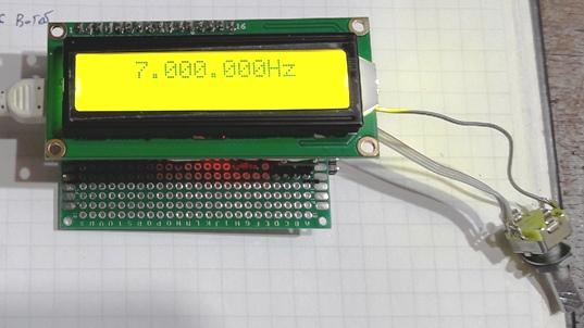
Um VFO simples com LCD de duas linhas 14 caracteres, arduino nano e o
SI5351.
Esquema :
As saidas defasadas estão nos clocks 0 e 1, pinos 9 e 10 do
SI5351.
Devido ao PLL interno do SI5351 trabalhar de 600 a 900MHz (o meu
esta até 880MHz) e a necessidade de usar um divisor par para
obter a quadratura e este divisor é limitado entre 0 e 127, o
maior divisor é 126.
Assim a menor frequencia obtida é 600/126=4,7619MHz.
Com a simples modificação de uma linha na biblioteca
(library), alterei a frequencia minima para 400MHz, foi possivel
atingir os 3,2MHz (400/126=3,174).
A maior frequencia possivel, gerando quadratura, foi com a
divisão por 8 assim o meu VFO ficou limitado a 110MHz (880/8).
Ainda testei o VFO, com a quadratura, até 30Mhz, como não
tenho equipamentos para testar uma frequencia maior, peço a
algum colega que monte este VFO que escreva dizendo dos resultados
(agora testei até 110MHz, acima disso não funciona).
Os meus sketches são simples funcionam, mas podem conter bugs,
não sou programador mas um simples curioso. Os sketches
são abertos a modificação, mas o uso comercial
deve ser visto com outros idealizadores do programa e biblioteca.
#(O Hans Summers G0UPL explica na apresentação do kit do
QCX que o SI5351 pode gerar quadratura no minimo a 3,2MHz, o que
não consegui, vou escrever a ele e ao Jason Milldrum NT7S, autor
da biblioteca para esclarecer como fazer.)#
Fiz alteração de uma linha na biblioteca do Jason Milldrum
NT7S, alterando a frequencia minima do PLL de 600MHz para 400MHz e
funcionou !
Em
um proximo trabalho farei um VFO, como este, mas com possibilidade
de ajuste independente do clock2, assim gerando um outro sinal
independente.
Outra modificação possivel é a inversão de
sinais de um dos cloks (0 ou 1) gerando um sinal de 0 a 270 graus, ao
inves de 0 a 90 graus, assim permitindo via software a inversão
de banda lateral em equipamentos SSB. Já testei um transceptor
SSB por fase (não SDR / sem o uso do PC) usando este VFO.
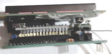
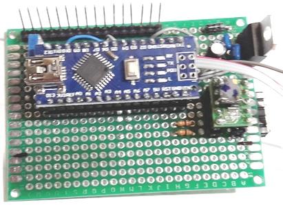
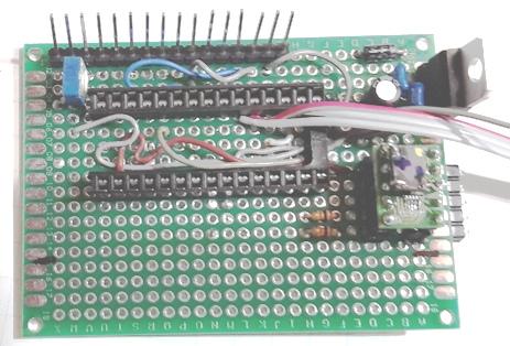
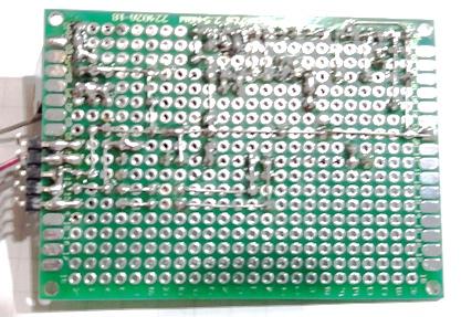
Montagem
Montei em uma placa padrão, montando como sandwich.
Não ficou boa pois o uso dos pinos digitais 2 e 3 do arduino, no
encoder é de uso exclusivo e foi necessario modificar.
Falta cortar o restante da placa sem uso.
Sketch
/*
This entire program is taken from Jason Mildrum, NT7S and Przemek
Sadowski, SQ9NJE.
There is not enough original code written by AK2b to make it worth
mentioning.
http://nt7s.com/
http://sq9nje.pl/
http://ak2b.blogspot.com/
I made some mods ...first updating the sketch to new library from NT7S
..in frequency coverage and the mode for frequency change..
pressing the encoder and turn it at same time ...it will move a
underline showing
the place where it is OK to change
XXXXXXXXXXXXXXXXXXXXXX
Now I made other mods ... is OK to use with SDR rigs ... the
clock0 and
clock1 are in the same frequency, but in 90 degrees phase out.. it is ok
from 3.2MHz to 110MHz (teoric) I tested with 30MHz and it was OK
(to reach 3.2MHz I changed the NT7S library)
I made a new function according Hans Summers, for dont have clicks
when change the frequency ...reseting the SI5351 only when the
evendivider is changed
http://py2ohh.w2c.com.br/
*/
#include <Rotary.h>
#include <si5351.h>
#include <Wire.h>
#include <LiquidCrystal.h>
#define F_MAX 22000000000UL
#define ENCODER_A
2
// Encoder pin A nano/uno pin D2
#define ENCODER_B
3
// Encoder pin B nano/uno pin D3
#define ENCODER_BTN 8
#define LCD_RS
12
// LCD pin 4 nano/uno pin D12
#define LCD_E
10
// LCD pin 6 nano/uno pin D10
#define LCD_D4
5
// LCD pin11 nano/uno pin D5
#define LCD_D5
4
// LCD pin12 nano/uno pin D4
#define LCD_D6
7
// LCD pin13 nano/uno pin D7
#define LCD_D7
6
// LCD pin14 nano/uno pin D6
LiquidCrystal lcd(LCD_RS, LCD_E, LCD_D4, LCD_D5, LCD_D6,
LCD_D7); // LCD - pin assignement in
Si5351 si5351;
Rotary r = Rotary(ENCODER_A, ENCODER_B);
volatile uint32_t vfo = 700000000ULL / SI5351_FREQ_MULT; //start freq
now 7MHz- change to suit
volatile uint32_t vfo2 = 300000000ULL / SI5351_FREQ_MULT;
volatile uint32_t radix = 100; //start step size -
change to suit
double vfomhz ;
boolean changed_f = 0;
boolean changed_f2 = 0;
String tbfo = "";
short und = 3; //controle do underline
short pot = 3; // controle de multiplicador
int evendivisor = 100;
int oldevendivisor = 0;
//#define Direct_conversion //What you see on display is what you get
/**************************************/
/* Interrupt service routine for */
/* encoder frequency
change */
/**************************************/
ISR(PCINT2_vect) {
unsigned char result = r.process();
if (result == DIR_CW)
set_frequency(1);
else if (result == DIR_CCW)
set_frequency(-1);
}
/**************************************/
/* Change the frequency and underline */
/* dir = 1
Increment
*/
/* dir = -1 Decrement
/**************************************/
void set_frequency(short dir)
{
if (!digitalRead(ENCODER_BTN)) {
lcd.setCursor( 12 - und, 0);
if (dir == 1) {
und += 1;
switch (und) {
case 4 :
und = 5;
break;
case 8 :
und = 9;
break;
case 12 :
und = 11;
break;
}
}
if (dir == -1) {
und += -1;
switch (und) {
case 4 :
und = 3;
break;
case 8 :
und = 7;
break;
case 0 :
und = 1;
break;
}
}
pot = und;
if (und > 3) (pot += -1);
if (und > 7) (pot += -1);
lcd.setCursor( 12 - und, 0);
lcd.cursor();
}
else
{ lcd.noCursor();
if (dir == 1)
vfo += radix;
if (dir == -1) {
if (vfo > radix ) {
vfo -= radix;
}
}
changed_f = 1;
}
}
/**************************************/
/* Read the button with debouncing */
/**************************************/
boolean get_button()
{
if (!digitalRead(ENCODER_BTN))
{
delay(20);
if (!digitalRead(ENCODER_BTN))
{
while (!digitalRead(ENCODER_BTN));
return 1;
}
}
return 0;
}
/**************************************/
/* Displays the
frequency
*/
/**************************************/
void display_frequency()
{
uint16_t f, g;
lcd.setCursor(1, 0);
f = (vfo ) / 1000000; //variable is now vfo
instead of 'frequency'
if (f < 100) {
lcd.print(' ');
}
if (f < 10) {
lcd.print(' ');
}
lcd.print(f);
lcd.print('.');
f = (vfo % 1000000) / 1000;
if (f < 100)
lcd.print('0');
if (f < 10)
lcd.print('0');
lcd.print(f);
lcd.print('.');
f = vfo % 1000;
if (f < 100)
lcd.print('0');
if (f < 10)
lcd.print('0');
lcd.print(f);
lcd.print("Hz");
}
void setup()
{
Serial.begin(19200);
lcd.begin(16,
2);
// Initialize and clear the LCD
lcd.clear();
Wire.begin();
si5351.set_correction(140); //**mine. There is a calibration
sketch in File/Examples/si5351Arduino-Jason
//where you can determine the correction by using the serial
monitor.
//initialize the Si5351
si5351.init(SI5351_CRYSTAL_LOAD_8PF, 27000000, 0); //If you're
using a 27Mhz crystal, put in 27000000 instead of 0
// 0 is the default crystal frequency of 25Mhz.
// si5351.init(SI5351_CRYSTAL_LOAD_8PF, 0, 0);
// si5351.set_pll(SI5351_PLL_FIXED, SI5351_PLLA);
// Set CLK0 to output the starting "vfo" frequency as set above
by vfo = ?
si5351.drive_strength(SI5351_CLK0,SI5351_DRIVE_8MA); //you can
set this to 2MA, 4MA, 6MA or 8MA
//be careful though - measure into 50ohms
si5351.set_freq_manual(vfo * SI5351_FREQ_MULT, evendivisor * vfo
* SI5351_FREQ_MULT, SI5351_CLK0);
si5351.set_freq_manual(vfo * SI5351_FREQ_MULT, evendivisor * vfo
* SI5351_FREQ_MULT, SI5351_CLK1);
si5351.set_phase(SI5351_CLK0, 0);
si5351.set_phase(SI5351_CLK1, evendivisor);
si5351.pll_reset(SI5351_PLLA);
pinMode(ENCODER_BTN, INPUT_PULLUP);
PCICR |= (1 <<
PCIE2); //
Enable pin change interrupt for the encoder
PCMSK2 |= (1 << PCINT18) | (1 << PCINT19);
sei();
display_frequency(); // Update the display
}
void loop()
{
// Update the display if the frequency has been changed
if (changed_f)
{
vfomhz = vfo / 10000;
if (vfomhz > 320) {//era476
display_frequency();
}
else {
lcd.setCursor(0, 1);
// lcd.print(vfomhz);
// delay(1000);
lcd.print("NOT BELOW 3.2MHz");
delay(1000);
lcd.setCursor(0, 1);
lcd.print("
");
}
if ((vfomhz > 11000)) {
lcd.print("NOT OVER 110MHz");
delay(1000);
lcd.setCursor(0, 1);
lcd.print("
");
}
//altera evendivisor
alteraevendivisor();
si5351.set_freq_manual(vfo * SI5351_FREQ_MULT,
evendivisor * vfo * SI5351_FREQ_MULT, SI5351_CLK0);
si5351.set_freq_manual(vfo * SI5351_FREQ_MULT,
evendivisor * vfo * SI5351_FREQ_MULT, SI5351_CLK1);
si5351.set_phase(SI5351_CLK0, 0);
si5351.set_phase(SI5351_CLK1, evendivisor);
if (evendivisor != oldevendivisor) { //reset if
evendivisor is changed
si5351.pll_reset(SI5351_PLLA);
oldevendivisor = evendivisor;
}
tbfo = "";
changed_f = 0;
}
if (get_button())
{
switch (pot)
{
case 1:
radix = 1;
break;
case 2:
radix = 10;
break;
case 3:
radix = 100;
break;
case 4:
radix = 1000;
break;
case 5:
radix = 10000;
break;
case 6:
radix = 100000;
break;
case 7:
radix = 1000000;
break;
case 8:
radix = 10000000;
break;
case 9:
radix = 100000000;
break;
}
}
}
void alteraevendivisor()
{
if (vfomhz < 685) {
evendivisor = 126;
}
if ((vfomhz >= 685) && (vfomhz < 950)) {
evendivisor = 88;
}
if ((vfomhz >= 950) && (vfomhz < 1360)) {
evendivisor = 64;
}
if ((vfomhz >= 1360) && (vfomhz < 1750)) {
evendivisor = 44;
}
if ((vfomhz >= 1750) && (vfomhz < 2500)) {
evendivisor = 34;
}
if ((vfomhz >= 2500) && (vfomhz < 3600)) {
evendivisor = 24;
}
if ((vfomhz >= 3600) && (vfomhz < 4500)) {
evendivisor = 18;
}
if ((vfomhz >= 4500) && (vfomhz < 6000)) {
evendivisor = 14;
}
if ((vfomhz >= 6000) && (vfomhz < 8000)) {
evendivisor = 10;
}
if ((vfomhz >= 8000) && (vfomhz < 11000)) {
evendivisor = 8;
}
//if ((vfomhz >= 10000) && (vfomhz < 14660)) {
// evendivisor = 6;
// }
// if ((vfomhz >= 15000) && (vfomhz < 22000)) {
// evendivisor = 4;
// }
}
73 de py2ohh miguel
jun 2018 # 03/2019