RECEPTOR
FM/OM/SW(AM SSB e CW) com SI4735 protótipo
RECEIVER FM/MW/SW(AM SSB and CW) with
SI4735 prototype
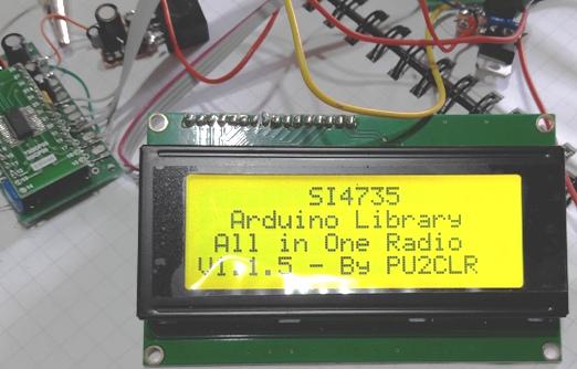
Tela
inicial
Home screen
No youtube tem um video
deste prototipo recebendo LSB
On youtube there is a video of this
prototype receiving LSB
Quando
tivemos a noticia que o Ricardo PU2CLR havia desenvolvido uma
biblioteca, compativel com Arduino, para o SI4735 e que esta biblioteca
permitiria receber SSB, resolvemos adquirir o integrado.
When we got the news that Ricardo
PU2CLR had developed a library, compatible with Arduino, for the SI4735
and that this library would allow receiving SSB, we decided to buy the
integrated one.
Depois de longa espera, recebemos o integrado e partimos para a
montagem de um prototipo, para avaliar o funcionamento do integrado
recebendo SSB.
O repositorio do Ricardo GitHub -pu2clr , tem
praticamente tudo que precisamos para montar o receptor.
After a long wait, we received the
integrated and started to assemble a prototype, to evaluate the
functioning of the integrated receiving SSB.
Ricardo's GitHub repository -pu2clr
, has practically everything we need to assemble the receiver.
Resolvi montar o "All
in one"
I build the "All
in one"
As caracteristicas do circuito são estas :
1. FM, OM e OC recebendo AM, LSB, USB.
2. Filtro de audio com largura de 0,5 1,0 1,2
2,2 3,0 e 4,0kHz.
3. 22 bandas entre de radioamadores e comerciais
pré-configuradas.
4. BFO ajustavel.
5. Passo de sintonia ajustavel de 1,0 5,0 e 10kHz
The characteristics of the circuit
are these:
1. FM, OM and OC receiving AM, LSB,
USB.
2. Audio filter with width of 0.5 1.0
1.2 2.2 3.0 and 4.0kHz.
3. 22 pre-configured commercial and
amateur radio bands.
4. Adjustable BFO.
5. Adjustable tuning step from 1.0,
5.0 and 10kHz
O esquema basico sugerido é este :
The basic schema suggested is this:
Como podemos observar o esquema basico é bem simples e se refere
a todas as montagens do Ricardo.
As we can see, the basic schema is
very simple and refers to all Ricardo assemblies.
Vamos a nossa montagem
Let's go to our montage
Esquema
:
Scheme:
O esquema ficou um pouco mais complicado pois acrescentamos tudo que
foi preciso para funcionar a partir de 12V e com o Arduino Nano.
The scheme got a little more
complicated because we added everything needed to work from 12V and
with the Arduino Nano.
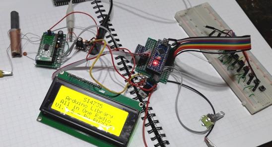
Prototipo montado esquerda para direita bobina de OM, SI4735 +fonte de
3,3V, amplificador de audio, conversor de nivel 5V para 3,3V junto com
o arduino nano e fonte de 5V, conjunto de chaves. Embaixo o LCD.
Prototype mounted left to right OM
coil, SI4735 +3.3V power supply, audio amplifier, 5V to 3.3V level
converter along with Arduino nano and 5V power supply, set of switches.
Underneath the LCD.
No lugar dos transistores Tr1 a Tr3 e R1 a R6 eu coloquei um conversor
de nivel bidirecional comprado da China.
In place of transistors Tr1 to Tr3
and R1 to R6 I put a bidirectional level converter bought from China.
Onde HV é ligado os 5V , em LV os 3,3V, em HV1 a HV4 as
conexões do Arduino nano, em LV1 a LV4 as conexões do
SI4735. E ambos os GND ligados a terra. Usei sómente tres dos
quatro conversores.
Where HV is connected to 5V, in LV
the 3.3V, in HV1 to HV4 the Arduino nano connections, in LV1 to LV4 the
SI4735 connections. And both GND connected to ground. I only used three
of the four converters.
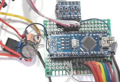
Foto : esquerda fonte de 5V, arduino nano com o conversor plugado e
cabos para as chaves.
Photo: left 5V power supply, arduino
nano with the converter plugged in and cables for the switches.
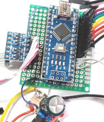
Foto: outro detalhe do arduino, conversor de nivel e fonte de 5V
Photo: another detail of the arduino,
level converter and 5V source
Para ler o endereço do I2C do LCD eu usei este sketch
To read the I2C address from the LCD I used this sketch
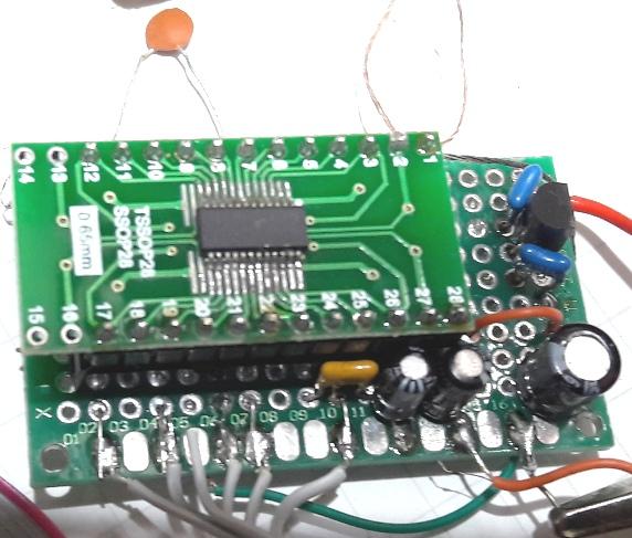
Foto: SI4735 soldado manualmente
Soldagem do CI
Para soldar o SI4735 eu usei somente a pasta XG-50 (Sn63 Pb37) e uma
placa
adaptadora (como não tinha uma de 24 pinos usei uma de 28
pinos). Tanto a pasta de solda como a placa adaptadora foram comprados
da China.
Para soldar o SI4735 na placa, eu costumo virar o CI com lides para
cima (inseto morto) e colocar a pasta nos lides, deixando eles cobertos
de pasta, mas o corpo de CI limpo.
Os lides do CI ficam então cobertos de pasta, e a pasta fica
entre os pinos tambem.
Coloco o CI na posição de montagem, pino 1 com
pino1, cuidando para que fique bem dividido ou seja não
fique muito de um lado e pouco de outro.
Soldo um pino da extremidade e verifico se o CI esta fixo e confiro se
os pinos estão alinhados com a PCB adptadora.
Estando fixo, eu soldo os outros pinos, procurando derreter toda a
pasta como soldador (uso um de 30W Hikari).
Passo a ponta do soldador entre os pinos eliminado o excesso.
Verifico a continuidade e os curtos com um Ohmimetro analogico escala
x1.
Se não há continuidade eu repasso o soldador.
Tendo curtos circuitos, ai fica mais dificil, mas com o soldador
simplesmente eu consigo eliminar a maioria os curtos. Os dificeis uso
uma malha (shield de cabo) ou uma cordoalha para sugar o excesso de
solda entre os pinos. É muito raro ter que dessoldar os CI para
solda-lo novamente.
Não uso lupas de aumento e nem dispositivos eletronicos (lupas).
Simplesmente tiro os oculos (tenho 3,5 graus de miopia em cada olho e
sem oculos a distancia fica perfeita para enxergar e soldar).
A pasta de solda tem boa durabilidade se guardada na geladeira.
IC welding
To solder the SI4735 I used only the
XG-50 paste (Sn63 Pb37) and an adapter plate (as I didn't have a 24-pin
one, I used a 28-pin one). Both solder paste and adapter plate were
purchased from China.
To solder the SI4735 to the board, I
usually turn the IC with the leads up (dead insect) and put the paste
on the leads, leaving them covered in paste, but the IC body clean.
The IC leads are then covered in
paste, and the paste is between the pins as well.
I place the IC in the mounting
position, pin 1 with pin1, taking care that it is well divided, that
is, it is not too much on one side and not too much on the other.
Solder a pin from the end and check
if the IC is fixed and check if the pins are aligned with the adapter
PCB.
Being fixed, I solder the other pins,
trying to melt all the paste as a welder (I use a 30W Hikari).
Pass the welder tip between the pins
to eliminate excess.
I check continuity and shorts with an
x1 scale analog ohmmeter.
If there's no continuity, I'll
replace the welder.
Having short circuits, it becomes
more difficult, but with the welder I can simply eliminate most of the
shorts. The hard ones use a mesh (cable shield) or a strand to suck the
excess solder between the pins. It is very rare to have to unsolder the
IC to solder it again.
I do not use magnifying glasses or
electronic devices (loupes). I simply take my glasses off (I have 3.5
degrees of myopia in each eye and without glasses the distance is
perfect for seeing and soldering).
Solder paste has a good shelf life if
stored in the refrigerator.
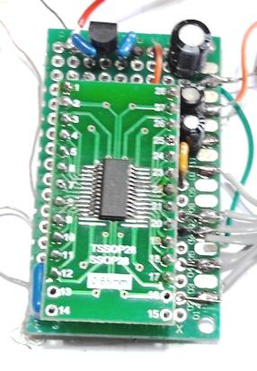
Foto : SI4735 soldado na placa de 28 pinos e plugado em uma PCB
padrão, o cristal capacitores ealguns resistores estão
soldados na pCB sob a placa adaptadora.
Nota :
Para quem mora no Brasil tem um vendedor, no mercado livre, que vende o
CI montado (soldado) na placa, já com o cristal de 32,768kHz e
os
capacitores de 22pF soldados.
O cristal de 32,768kHz eu tinha de sucata. Este cristal é
facilmente encontrado em placas de PC ou outras como clock, são
pequenos e cilindricos.
O regulador 7805, 78L33, LCD, encoder e o adaptador para LCD I2C :
comprei da China.
Photo: SI4735 soldered on the 28-pin
board and plugged into a standard PCB, the crystal capacitors and some
resistors are soldered on the pCB under the adapter board.
Note :
For those who live in Brazil, there
is a seller, on the free market, who sells the IC mounted (soldered) on
the board, already with the 32.768kHz crystal and the 22pF capacitors
soldered.
The 32.768kHz crystal I had scrap.
This crystal is easily found in PC boards or other like clock, they are
small and cylindrical.
The 7805, 78L33, LCD, encoder and
adapter for LCD I2C : I bought it from China.
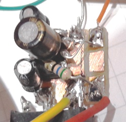
Foto: modulo do amplificador de audio, montado em modulo (15x 15mm)
inseto morto
O amplificador de audio pode ser eliminado se usar fones ou se utilisar
mini falantes amplificados (estereo). Ou então usar um
amplificador estereo de 3W (CI PAM8403 5V) que é vendido montado
ou similar.
Como devo usar o radio para receber ondas curtas preferi montar um
LM386 mono. A montagem foi feita em um pequeno modulo (15x15mm),
montando o LM386 como inseto morto.
Photo: audio amplifier module,
mounted on module (15x 15mm) dead insect
The audio amplifier can be eliminated
if you use headphones or if you use mini amplified (stereo) speakers.
Or use a 3W stereo amplifier (CI PAM8403 5V) that is sold assembled or
similar.
As I should use the radio to receive
short waves I preferred to mount a LM386 mono. The assembly was done in
a small module (15x15mm), mounting the LM386 as a dead bug.
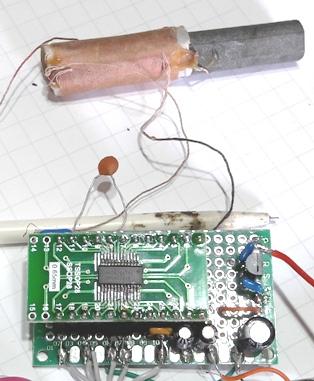
Foto Si4735 e a bobina de OM, usamos a derivação para
ligar a antena. Para a banda LW abaixo de 500kHz recomendaoms colocar
duas bobinas de OM em serie. Podendo uma ser jampeada para oucir OM
(MW).
Photo Si4735 and the OM coil, we use
the shunt to connect the antenna. For the LW band below 500kHz, we
recommend placing two OM coils in series. One can be jammed to hear OM
(MW).
A bobina de antena usei uma da sucata semelhante a que tinha usado na montagem do SI4825
The antenna coil I used a scrap
similar to the one I had used in the assembly of the SI4825
Para carregar o sketch usei a IDE 1.8.9 copiada (e usada) a partir de
um pendrive. Para não dar conflito com a IDE usada anteriormente
eu renomeio a pasta Ardunio (ex. para xxArduino) que contem os sketches
e livrarias anteriores. O uso da outra IDE criará uma nova pasta
Arduino (não esqueça de voltar tudo ao que era).
To load the sketch I used the IDE
1.8.9 copied (and used) from a pendrive. In order not to conflict with
the IDE used previously, I rename the Ardunio folder (eg for xxArduino)
which contains the previous sketches and libraries. Using the other IDE
will create a new Arduino folder (don't forget to reset everything to
what it was).
Como o sketch do Ricardo tinha um conflito com o uso do pino D13,
mudamos para A2 alterando o codigo correspondente e adicionamos um
resistor para deixar o nivel de entrada em HI.
No software alteramos a linha 95 :
de :
As Ricardo's sketch had a conflict
with the use of pin D13, we changed it to A2 changing the corresponding
code and added a resistor to leave the input level at HI.
In the software we change line 95 :
in :
#define BFO_SWITCH 13 // Used to select
the enconder control (BFO or VFO)
para :
#define BFO_SWITCH A2 // Used to select
the enconder control (BFO or VFO)
e a linha 201
de :
pinMode(BFO_SWITCH, INPUT_PULLUP);
para:
pinMode(BFO_SWITCH, INPUT);//modificado para uno
Explicação :
No pino D13 (digital 13 ) do arduino nano tem um LED ligado do pino D13
ao terra, qdo o resistor interno (pullup), é acionado por
software o led acende, mas a tensão Hi não é muito
alta pois tem a tesão que esta acionando o LED cerca de 2,1V.
Como foi usadas todos os pinos digitais (tipo D), usamos uma porta
analogica como digital (A2) e necessitamos adicionar um resistor para
deixar esta porta em Hi (nas portas A analogicas não tem a
função que lga os resistores internos como nas portas
digitais D) como era no sketch do Ricardo
Alteramos tambem o
endereço do I2C do LCD obtido como descrito anteriormente. Este
endereço foi 0x3F caso o endereço que voce obteve, no seu
LCD +I2C , voce deve alterar na linha numero 187 :
este é a linha do Ricardo
LiquidCrystal_I2C display(0x27, 20, 4); // please check the address of
your I2C device
a minha linha ficou assim :
LiquidCrystal_I2C display(0x3F, 20, 4); // please check the address of
your I2C device
O software tem a possibilidade de carregar os arquivos patch_ini.h
ou patch_full.h carregamos uma a cada vez e não observamos
diferenças.
No hardware usamos o pino 16 ligado a terra (endereço 0x11).
O sketch modificado pode ser obtido neste arquivo
Gostariamos de agradecer ao PU2CLR Ricardo pelo excelente trabalho
realizado !
Explanation :
On pin D13 (digital 13) of the
arduino nano there is an LED connected from pin D13 to ground, when the
internal resistor (pullup) is activated by software the led lights up,
but the Hi voltage is not very high because it is horny driving the LED
about 2.1V.
As all digital pins (D type) were
used, we used an analog port as a digital one (A2) and we need to add a
resistor to leave this port in Hi (on analog ports A does not have the
function that connects the internal resistors as in digital ports D) as
it was in Ricardo's sketch
We also changed the LCD I2C address
obtained as described above. This address was 0x3F if the address you
got, on your LCD +I2C , you must change it on line number 187:
this is Ricardo's line
LiquidCrystal_I2C display(0x27, 20,
4); // please check the address of your I2C device
my line looked like this:
LiquidCrystal_I2C display(0x3F, 20,
4); // please check the address of your I2C device
The software has the possibility to
load the files patch_ini.h or patch_full.h we load them one at a time
and we didn't notice any differences.
In hardware we use pin 16 connected
to ground (address 0x11).
The modified sketch can be obtained
from this File
We would like to thank PU2CLR Ricardo
for the excellent work done!
73 de py2ohh miguel
Aqui esta o sketch :
/*
SI4735 all in one with SSB Support
This sketch has been successfully tested on:
1) Pro Mini 3.3V;
2) UNO (by using a voltage converter);
3) Arduino Yún (by using a voltage converter);
4) Arduino Micro (see the operating voltage of your Micro);
5) Arduino Mega (by using a voltage converter); and
6) Arduino DUE;
This sketch uses I2C LiquidCrystal/LCD, buttons and
Encoder.
This sketch uses the Rotary Encoder Class implementation from
Ben Buxton (the source code is included
together with this sketch) and LiquidCrystal I2C Library by
Frank de Brabander (https://github.com/johnrickman/LiquidCrystal_I2C).
Look for LiquidCrystal I2C on Manager Libraries.
ABOUT DIGITAL pin 13 and INPUT PULL-UP on Arduino Pro Mini, UNO
or similar:
This pin has a LED and a resistor connected on the board. When
this pin is set to HIGH the LED comes on. If you use the internal
pull-up resistor of the pin 13, you might experiment problem due
to the drop voltage caused by the LED circuit.
If this occurs in your project, change the circuit to use
external pull-up on pin 13.
ABOUT SSB PATCH:
This sketch will download a SSB patch to your SI4735 device
(patch_init.h). It will take about 8KB of the Arduino memory.
In this context, a patch is a piece of software used to change
the behavior of the SI4735 device.
There is little information available about patching the SI4735.
The following information is the understanding of the author of
this project and it is not necessarily correct. A patch is
executed internally (run by internal MCU) of the device.
Usually, patches are used to fixes bugs or add improvements and
new features of the firmware installed in the internal ROM of the
device.
Patches to the SI4735 are distributed in binary form and have to
be transferred to the internal RAM of the device by
the host MCU (in this case Arduino). Since the RAM is volatile
memory, the patch stored into the device gets lost when you turn off
the system.
Consequently, the content of the patch has to be transferred
again to the device each time after turn on the system or reset the
device.
ATTENTION: The author of this project does not guarantee that
procedures shown here will work in your development environment.
Given this, it is at your own risk to continue with the
procedures suggested here.
This library works with the I2C communication protocol and it is
designed to apply a SSB extension PATCH to CI SI4735-D60.
Once again, the author disclaims any liability for any damage
this procedure may cause to your SI4735 or other devices that you are
using.
Features of this sketch:
1) FM, AM (MW and SW) and SSB (LSB and USB);
2) Audio bandwidth filter 0.5, 1, 1.2, 2.2, 3 and 4Khz;
3) 22 commercial and ham radio bands pre configured;
4) BFO Control; and
5) Frequency step switch (1, 5 and 10KHz);
Main Parts:
Encoder with push button;
Seven bush buttons;
LCD20x4 with I2C device;
Arduino Pro mini 3.3V;
Prototype documentation : https://pu2clr.github.io/SI4735/
PU2CLR Si47XX API documentation:
https://pu2clr.github.io/SI4735/extras/apidoc/html/
By Ricardo Lima Caratti, Nov 2019.
*/
#include <SI4735.h>
#include <LiquidCrystal_I2C.h>
#include "Rotary.h"
// Test it with patch_init.h or patch_full.h. Do not try load both.
#include "patch_init.h" // SSB patch for whole SSBRX initialization
string
//#include "patch_full.h" // SSB patch for whole
SSBRX full download
const uint16_t size_content = sizeof ssb_patch_content; // see
ssb_patch_content in patch_full.h or patch_init.h
#define FM_BAND_TYPE 0
#define MW_BAND_TYPE 1
#define SW_BAND_TYPE 2
#define LW_BAND_TYPE 3
// OLED Diaplay constants
#define I2C_ADDRESS 0x3C
#define RST_PIN -1 // Define proper RST_PIN if required.
#define RESET_PIN 12
// Enconder PINs
#define ENCODER_PIN_A 3
#define ENCODER_PIN_B 2
// Buttons controllers
#define MODE_SWITCH 4 // Switch MODE
(Am/LSB/USB)
#define BANDWIDTH_BUTTON 5 // Used to select the banddwith. Values:
1.2, 2.2, 3.0, 4.0, 0.5, 1.0 KHz
#define VOL_UP
6 // Volume
Up
#define VOL_DOWN 7 //
Volume Down
#define BAND_BUTTON_UP 8 // Next band
#define BAND_BUTTON_DOWN 9 // Previous band
#define AGC_SWITCH 11 // Switch AGC ON/OF
#define STEP_SWITCH 10 // Used to select the
increment or decrement frequency step (1, 5 or 10 KHz)
#define BFO_SWITCH A2 // Used to select
the enconder control (BFO or VFO)
#define MIN_ELAPSED_TIME 100
#define MIN_ELAPSED_RSSI_TIME 150
#define DEFAULT_VOLUME 15 // change it for your favorite sound volume
#define FM 0
#define LSB 1
#define USB 2
#define AM 3
#define LW 4
#define SSB 1
const char *bandModeDesc[] = {"FM ", "LSB", "USB", "AM "};
uint8_t currentMode = FM;
bool bfoOn = false;
bool disableAgc = true;
bool ssbLoaded = false;
bool fmStereo = true;
int currentBFO = 0;
int previousBFO = 0;
long elapsedRSSI = millis();
long elapsedButton = millis();
long elapsedFrequency = millis();
// Encoder control variables
volatile int encoderCount = 0;
// Some variables to check the SI4735 status
uint16_t currentFrequency;
uint16_t previousFrequency;
uint8_t currentStep = 1;
uint8_t currentBFOStep = 25;
uint8_t bwIdxSSB = 2;
const char *bandwitdthSSB[] = {"1.2", "2.2", "3.0", "4.0", "0.5",
"1.0"};
uint8_t bwIdxAM = 1;
const char *bandwitdthAM[] = {"6", "4", "3", "2", "1", "1.8", "2.5"};
/*
Band data structure
*/
typedef struct
{
uint8_t bandType; // Band type (FM, MW
or SW)
uint16_t minimumFreq; // Minimum frequency of the band
uint16_t maximumFreq; // maximum frequency of the band
uint16_t currentFreq; // Default frequency or current frequency
uint16_t currentStep; // Defeult step (increment and decrement)
} Band;
/*
Band table
*/
Band band[] = {
{FM_BAND_TYPE, 8400, 10800, 10390, 10},
{LW_BAND_TYPE, 100, 510, 300, 1},
{MW_BAND_TYPE, 520, 1720, 810, 10},
{SW_BAND_TYPE, 1800, 3500, 1900, 1}, // 160 meters
{SW_BAND_TYPE, 3500, 4500, 3700, 1}, // 80 meters
{SW_BAND_TYPE, 4500, 5500, 4850, 5},
{SW_BAND_TYPE, 5600, 6300, 6000, 5},
{SW_BAND_TYPE, 6800, 7800, 7200, 5}, // 40 meters
{SW_BAND_TYPE, 9200, 10000, 9600, 5},
{SW_BAND_TYPE, 10000, 11000, 10100, 1}, // 30 meters
{SW_BAND_TYPE, 11200, 12500, 11940, 5},
{SW_BAND_TYPE, 13400, 13900, 13600, 5},
{SW_BAND_TYPE, 14000, 14500, 14200, 1}, // 20 meters
{SW_BAND_TYPE, 15000, 15900, 15300, 5},
{SW_BAND_TYPE, 17200, 17900, 17600, 5},
{SW_BAND_TYPE, 18000, 18300, 18100, 1}, // 17 meters
{SW_BAND_TYPE, 21000, 21900, 21200, 1}, // 15 mters
{SW_BAND_TYPE, 24890, 26200, 24940, 1}, // 12 meters
{SW_BAND_TYPE, 26200, 27900, 27500, 1}, // CB band (11
meters)
{SW_BAND_TYPE, 28000, 30000, 28400, 1}
}; // 10 meters
const int lastBand = (sizeof band / sizeof(Band)) - 1;
int bandIdx = 0;
uint8_t rssi = 0;
uint8_t stereo = 1;
uint8_t volume = DEFAULT_VOLUME;
// Devices class declarations
Rotary encoder = Rotary(ENCODER_PIN_A, ENCODER_PIN_B);
LiquidCrystal_I2C display(0x3F, 20, 4); // please check the address of
your I2C device
SI4735 si4735;
void setup()
{
// Encoder pins
pinMode(ENCODER_PIN_A, INPUT_PULLUP);
pinMode(ENCODER_PIN_B, INPUT_PULLUP);
pinMode(BANDWIDTH_BUTTON, INPUT_PULLUP);
pinMode(BAND_BUTTON_UP, INPUT_PULLUP);
pinMode(BAND_BUTTON_DOWN, INPUT_PULLUP);
pinMode(VOL_UP, INPUT_PULLUP);
pinMode(VOL_DOWN, INPUT_PULLUP);
pinMode(BFO_SWITCH, INPUT);//modificado para uno
pinMode(AGC_SWITCH, INPUT_PULLUP);
pinMode(STEP_SWITCH, INPUT_PULLUP);
pinMode(MODE_SWITCH, INPUT_PULLUP);
display.init();
delay(500);
// Splash - Change it for your introduction text.
display.backlight();
display.setCursor(7, 0);
display.print("SI4735");
display.setCursor(2, 1);
display.print("Arduino Library");
delay(500);
display.setCursor(1, 2);
display.print("All in One Radio");
delay(500);
display.setCursor(0, 3);
display.print("V1.1.5 - By PU2CLR");
delay(2000);
// end Splash
// Encoder interrupt
attachInterrupt(digitalPinToInterrupt(ENCODER_PIN_A),
rotaryEncoder, CHANGE);
attachInterrupt(digitalPinToInterrupt(ENCODER_PIN_B),
rotaryEncoder, CHANGE);
si4735.setup(RESET_PIN, FM_BAND_TYPE);
// Set up the radio for the current band (see index table
variable bandIdx )
useBand();
delay(200);
currentFrequency = previousFrequency = si4735.getFrequency();
si4735.setVolume(volume);
display.clear();
showStatus();
}
// Use Rotary.h and Rotary.cpp implementation to process encoder
via interrupt
void rotaryEncoder()
{ // rotary encoder events
uint8_t encoderStatus = encoder.process();
if (encoderStatus)
{
if (encoderStatus == DIR_CW)
{
encoderCount = 1;
}
else
{
encoderCount = -1;
}
}
}
void clearLine4() {
display.setCursor(0, 2);
display.print("
");
}
// Show current frequency
void showFrequency()
{
String freqDisplay;
String unit;
String bandMode;
int divider = 1;
int decimals = 3;
if (band[bandIdx].bandType == FM_BAND_TYPE)
{
divider = 100;
decimals = 1;
unit = "MHz";
}
else if (band[bandIdx].bandType == MW_BAND_TYPE ||
band[bandIdx].bandType == LW_BAND_TYPE)
{
divider = 1;
decimals = 0;
unit = "KHz";
}
else
{
divider = 1000;
decimals = 3;
unit = "KHz";
}
if ( !bfoOn )
freqDisplay = String((float)currentFrequency /
divider, decimals);
else
freqDisplay = ">" +
String((float)currentFrequency / divider, decimals) + "<";
display.setCursor(7, 0);
display.print(" ");
display.setCursor(7, 0);
display.print(freqDisplay);
if (currentFrequency < 520 )
bandMode = "LW ";
else
bandMode = bandModeDesc[currentMode];
display.setCursor(0, 0);
display.print(bandMode);
display.setCursor(17, 0);
display.print(unit);
}
/*
Show some basic information on display
*/
void showStatus()
{
showFrequency();
display.setCursor(13, 1);
display.print(" ");
display.setCursor(13, 1);
display.print("St: ");
display.print(currentStep);
display.setCursor(0, 3);
display.print("
");
display.setCursor(0, 3);
if (currentMode == LSB || currentMode == USB)
{
display.print("BW:");
display.print(String(bandwitdthSSB[bwIdxSSB]));
display.print("KHz");
showBFO();
}
else if (currentMode == AM)
{
display.print("BW:");
display.print(String(bandwitdthAM[bwIdxAM]));
display.print("KHz");
}
// Show AGC Information
si4735.getAutomaticGainControl();
display.setCursor(0, 1);
display.print((si4735.isAgcEnabled()) ? "AGC ON " : "AGC OFF");
showRSSI();
showVolume();
}
/* *******************************
Shows RSSI status
*/
void showRSSI()
{
int bars = ((rssi / 10.0) / 2.0) + 1;
display.setCursor(13, 3);
display.print(" ");
display.setCursor(13, 3);
display.print("S:");
if ( bars > 5 ) {
bars = 5;
}
for (int i = 0; i < bars; i++)
display.print(">");
if ( currentMode == FM) {
display.setCursor(0, 3);
display.print((si4735.getCurrentPilot()) ?
"STEREO " : "MONO ");
}
}
/*
Shows the volume level on LCD
*/
void showVolume()
{
display.setCursor(10, 3);
display.print(" ");
display.setCursor(10, 3);
display.print(si4735.getCurrentVolume());
}
/*
Shows the BFO current status.
Must be called only on SSB mode (LSB or USB)
*/
void showBFO()
{
String bfo;
if (currentBFO > 0)
bfo = "+" + String(currentBFO);
else
bfo = String(currentBFO);
display.setCursor(0, 2);
display.print("
");
display.setCursor(0, 2);
display.print("BFO:");
display.print(bfo);
display.print("Hz ");
display.setCursor(13, 2);
display.print(" ");
display.setCursor(13, 2);
display.print("St: ");
display.print(currentBFOStep);
}
/*
Goes to the next band (see Band table)
*/
void bandUp()
{
// save the current frequency for the band
band[bandIdx].currentFreq = currentFrequency;
band[bandIdx].currentStep = currentStep;
if (bandIdx < lastBand)
{
bandIdx++;
}
else
{
bandIdx = 0;
}
useBand();
}
/*
Goes to the previous band (see Band table)
*/
void bandDown()
{
// save the current frequency for the band
band[bandIdx].currentFreq = currentFrequency;
band[bandIdx].currentStep = currentStep;
if (bandIdx > 0)
{
bandIdx--;
}
else
{
bandIdx = lastBand;
}
useBand();
}
/*
This function loads the contents of the ssb_patch_content
array into the CI (Si4735) and starts the radio on
SSB mode.
*/
void loadSSB()
{
display.setCursor(0, 2);
display.print(" Switching to SSB ");
si4735.reset();
si4735.queryLibraryId(); // Is it really necessary here?
Just powerDown() maigh work!
si4735.patchPowerUp();
delay(50);
// si4735.setI2CFastMode(); // Recommended
si4735.setI2CFastModeCustom(500000); // It is a test and may
crash.
si4735.downloadPatch(ssb_patch_content, size_content);
si4735.setI2CStandardMode(); // goes back to default (100KHz)
clearLine4();
// delay(50);
// Parameters
// AUDIOBW - SSB Audio bandwidth; 0 = 1.2KHz (default);
1=2.2KHz; 2=3KHz; 3=4KHz; 4=500Hz; 5=1KHz;
// SBCUTFLT SSB - side band cutoff filter for band passand low
pass filter ( 0 or 1)
// AVC_DIVIDER - set 0 for SSB mode; set 3 for SYNC mode.
// AVCEN - SSB Automatic Volume Control (AVC) enable; 0=disable;
1=enable (default).
// SMUTESEL - SSB Soft-mute Based on RSSI or SNR (0 or 1).
// DSP_AFCDIS - DSP AFC Disable or enable; 0=SYNC MODE, AFC
enable; 1=SSB MODE, AFC disable.
si4735.setSSBConfig(bwIdxSSB, 1, 0, 0, 0, 1);
delay(25);
ssbLoaded = true;
display.clear();
}
/*
Switch the radio to current band.
The bandIdx variable points to the current band.
This function change to the band referenced by bandIdx
(see table band).
*/
void useBand()
{
clearLine4();
if (band[bandIdx].bandType == FM_BAND_TYPE)
{
currentMode = FM;
si4735.setTuneFrequencyAntennaCapacitor(0);
si4735.setFM(band[bandIdx].minimumFreq,
band[bandIdx].maximumFreq, band[bandIdx].currentFreq,
band[bandIdx].currentStep);
bfoOn = ssbLoaded = false;
}
else
{
if (band[bandIdx].bandType == MW_BAND_TYPE ||
band[bandIdx].bandType == LW_BAND_TYPE)
si4735.setTuneFrequencyAntennaCapacitor(0);
else
si4735.setTuneFrequencyAntennaCapacitor(1);
if (ssbLoaded)
{
si4735.setSSB(band[bandIdx].minimumFreq,
band[bandIdx].maximumFreq, band[bandIdx].currentFreq,
band[bandIdx].currentStep, currentMode);
si4735.setSSBAutomaticVolumeControl(1);
si4735.setSsbSoftMuteMaxAttenuation(0);
// Disable Soft Mute for SSB
}
else
{
currentMode = AM;
si4735.setAM(band[bandIdx].minimumFreq,
band[bandIdx].maximumFreq, band[bandIdx].currentFreq,
band[bandIdx].currentStep);
si4735.setAutomaticGainControl(1, 0);
si4735.setAmSoftMuteMaxAttenuation(0);
// // Disable Soft Mute for AM
bfoOn = false;
}
}
delay(100);
currentFrequency = band[bandIdx].currentFreq;
currentStep = band[bandIdx].currentStep;
showStatus();
}
void loop()
{
// Check if the encoder has moved.
if (encoderCount != 0)
{
if (bfoOn)
{
currentBFO = (encoderCount == 1) ?
(currentBFO + currentBFOStep) : (currentBFO - currentBFOStep);
}
else
{
if (encoderCount == 1)
si4735.frequencyUp();
else
si4735.frequencyDown();
// Show the current frequency only if it
has changed
currentFrequency = si4735.getFrequency();
}
encoderCount = 0;
}
// Check button commands
if ((millis() - elapsedButton) > MIN_ELAPSED_TIME)
{
// check if some button is pressed
if (digitalRead(BANDWIDTH_BUTTON) == LOW)
{
if (currentMode == LSB || currentMode ==
USB)
{
bwIdxSSB++;
if (bwIdxSSB > 5)
bwIdxSSB = 0;
si4735.setSSBAudioBandwidth(bwIdxSSB);
// If audio bandwidth
selected is about 2 kHz or below, it is recommended to set Sideband
Cutoff Filter to 0.
if (bwIdxSSB == 0 ||
bwIdxSSB == 4 || bwIdxSSB == 5)
si4735.setSBBSidebandCutoffFilter(0);
else
si4735.setSBBSidebandCutoffFilter(1);
}
else if (currentMode == AM)
{
bwIdxAM++;
if (bwIdxAM > 6)
bwIdxAM = 0;
si4735.setBandwidth(bwIdxAM,
1);
}
showStatus();
delay(MIN_ELAPSED_TIME); // waits a
little more for releasing the button.
}
else if (digitalRead(BAND_BUTTON_UP) == LOW)
bandUp();
else if (digitalRead(BAND_BUTTON_DOWN) == LOW)
bandDown();
else if (digitalRead(VOL_UP) == LOW)
{
si4735.volumeUp();
delay(MIN_ELAPSED_TIME); // waits a
little more for releasing the button.
}
else if (digitalRead(VOL_DOWN) == LOW)
{
si4735.volumeDown();
delay(MIN_ELAPSED_TIME); // waits a
little more for releasing the button.
}
else if (digitalRead(BFO_SWITCH) == LOW)
{
if (currentMode == LSB || currentMode ==
USB) {
bfoOn = !bfoOn;
if (bfoOn)
showBFO();
showStatus();
} else if (currentMode == FM) {
si4735.seekStationUp();
delay(30);
currentFrequency =
si4735.getFrequency();
}
delay(MIN_ELAPSED_TIME); // waits a
little more for releasing the button.
}
else if (digitalRead(AGC_SWITCH) == LOW)
{
disableAgc = !disableAgc;
// siwtch on/off ACG; AGC Index = 0. It
means Minimum attenuation (max gain)
si4735.setAutomaticGainControl(disableAgc, 1);
showStatus();
}
else if (digitalRead(STEP_SWITCH) == LOW)
{
if ( currentMode == FM) {
fmStereo = !fmStereo;
if ( fmStereo )
si4735.setFmStereoOn();
else
si4735.setFmStereoOff(); // It is not working so far.
} else {
// This command should work
only for SSB mode
if (bfoOn &&
(currentMode == LSB || currentMode == USB))
{
currentBFOStep =
(currentBFOStep == 25) ? 10 : 25;
showBFO();
}
else
{
if (currentStep
== 1)
currentStep = 5;
else if
(currentStep == 5)
currentStep = 10;
else
currentStep = 1;
si4735.setFrequencyStep(currentStep);
band[bandIdx].currentStep = currentStep;
showStatus();
}
delay(MIN_ELAPSED_TIME); //
waits a little more for releasing the button.
}
}
else if (digitalRead(MODE_SWITCH) == LOW)
{
if (currentMode != FM ) {
if (currentMode == AM)
{
// If you were
in AM mode, it is necessary to load SSB patch (avery time)
loadSSB();
currentMode =
LSB;
}
else if (currentMode == LSB)
{
currentMode =
USB;
}
else if (currentMode == USB)
{
currentMode = AM;
ssbLoaded =
false;
bfoOn = false;
}
// Nothing to do if you are
in FM mode
band[bandIdx].currentFreq =
currentFrequency;
band[bandIdx].currentStep =
currentStep;
useBand();
}
}
elapsedButton = millis();
}
// Show the current frequency only if it has changed
if (currentFrequency != previousFrequency)
{
previousFrequency = currentFrequency;
showFrequency();
}
// Show RSSI status only if this condition has changed
if ((millis() - elapsedRSSI) > MIN_ELAPSED_RSSI_TIME * 12)
{
si4735.getCurrentReceivedSignalQuality();
int aux = si4735.getCurrentRSSI();
if (rssi != aux)
{
rssi = aux;
showRSSI();
}
elapsedRSSI = millis();
}
// Show volume level only if this condition has changed
if (si4735.getCurrentVolume() != volume)
{
volume = si4735.getCurrentVolume();
showVolume();
}
if (currentMode == LSB || currentMode == USB)
{
if (currentBFO != previousBFO)
{
previousBFO = currentBFO;
si4735.setSSBBfo(currentBFO);
showBFO();
}
}
delay(10);
}