µSDX
PEANUTS COOKER amplificador LINEAR
µSDX
PEANUTS COOKER LINEAR amplifier
Este
linear montamos para operar CW e SSB nas faixas de 80 a 15m, junto com
o µSDX fica um radio simples e barato para uso em casa.
Procuramos ter um circuito simples, com material de relativa facilidade
de aquisição.
This linear we set up to operate CW
and SSB in the 80 to 15m bands, together with the µSDX it becomes
a simple and inexpensive radio for use at home.
We try to have a simple circuit, with
material of relative ease of acquisition.
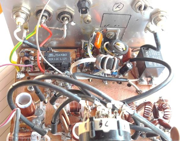
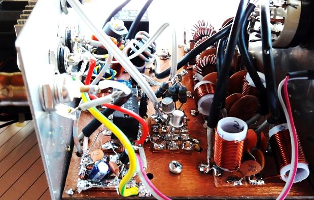
Foto : Minha montagem não é bonita ...mas
funciona.
Picture: My building is not pretty
... but it works.
A potencia varia de 7W (13,8V em 15m) até 28W (22V em 80m)
confira na tabela (com alimentação do dreno do PA
com
13,8 ou 22V) :
Faixa 13,8V 22V
Corrente (A)
80m 14,5W 28W
1,2A
40m 17W
22,5W 1,2A
20m 10W
17W
0,8A
15m 7W
12W
1A
Estes
resultados foram obtidos com o µSDX operando com 3 a
3,5W
de saida.
The power varies from 7W (13.8V in
15m) to 28W (22V in 80m) check in the table (with PA drain supply
with 13.8 or 22V):
Band
13.8V 22V
Current (A)
80m 14.5W 28W
1.2A
40m 17W
22.5W 1.2A
20m 10W
17W
0.8A
15m 7W
12W
1A
These results were obtained with the µSDX operating with 3 to
3.5W output.
Esquema (Schematic):
Escolhi o IRF530 pois produz um pouco mais de potencia nas bandas de 40
e 80m, mas poderia ser o IRF510 ou o IRF610 que funciona bem
até
50V, de alimentação e produz um potencia maior
nas bandas
de 15 e 20m.
A mudança de banda é feita manualmente por uma
chave 2x4,
encontrada nos sites chineses com material plastico. Pode ser usada
para potencias até 40W (nominal max 90V e max 1,3A SWR 2:1).
As
conexões foram com cabo coaxial RG174.
I chose the IRF530 because it
produces a little more power in the 40 and 80m bands, but it could be
the IRF510 or the IRF610 that works well up to 50V, of power and
produces a greater power in the bands of 15 and 20m.
The band change is done manually by a
2x4 key, found on Chinese websites ( plastic material). It can be used
for powers up to 40W (nominal max 90V and max 1.3A SWR 2: 1). The
connections were with RG174 coaxial cable.
Os resistores do PAD de 6dB (150R e 39R) devem ser de metal filme com
potencia de 2W.
A chave TR acionada por RF tem um tempo de retardo em
função da carga do capacitor eletrolitico de
47µF,
caso o tempo esteja curto adicione um outro eletrolitico de
22µF
em paralelo.
O transistor 2N3904 pode ser substituido por um 2N2222 ou outro NPN de
uso geral.
O rele RL1 é de 12V tem 2 polos e
posições e tem a
capacidade de 1A em 120V, atendendo até 10W ( nominal max
45V e
max 0,63A com SWR 2:1= carga de 25R ou 100R).
O rele RL2 já opera com maior potencia é de 12V 1
polo 2
posições e tem a capacidade de 10A em 120V
atendendo
até 100W (nominal max 140V e max 2A com SWR 2:1).
The 6dB PAD resistors (150R and 39R)
must be made of metal film with a power of 2W.
The RF-activated TR switch has a
delay time depending on the load of the electrolytic capacitor of
47µF, if the time is short add another 22µF electrolytic in
parallel.
The 2N3904 transistor can be replaced
by a 2N2222 or another general purpose NPN.
The RL1 relay is 12V has 2 poles and
positions and has the capacity of 1A at 120V, serving up to 10W
(nominal max 45V and max 0.63A with SWR 2: 1 = 25R or 100R load).
The relay RL2 already operates with
greater power is 12V 1 pole 2 positions and has the capacity of 10A in
120V serving up to 100W (nominal max 140V and max 2A with SWR 2: 1).
Os toroide utilizados FT37-43, podem ser comprados no Brasil
codigo NT10/5/3,2 ou NT10/5/3,5.
Já o ferrite do choque FT50-B-43, no Brasil codigo
NT15/9,5/8 ou
NT15/9,5/12 (15 diametro externo, 9,5 diametro interno, 8 ou
12
altura ou largura). Este ferrite pode ser substituidos por 3x FT37-43
emplihados.
O ferrite BN4302 binocular (tipo balum), no Brasil
código
NBN 13/8/6/4.
Os fios para o choque e para o binocular devem suportar 2 ou mais
amperes e ter capa plastica.
The toroids used FT37-43, can be
purchased in Brazil code NT10 / 5 / 3,2 or NT10 / 5 / 3,5.
The shock ferrite FT50-B-43, in
Brazil code NT15 / 9.5 / 8 or NT15 / 9.5 / 12 (15 outer diameter, 9.5
inner diameter, 8 or 12 height or width). This ferrite can be replaced
by 3x FT37-43 fitted and glued with fast glue.
BN4302 binocular ferrite (balum
type), in Brazil code NBN 13/8/6/4.
The shock and binocular wires must
support 2 or more amps and have a plastic cover.
Os capacitores do PA de 250V devem ser de poliester.
Os capacitores do filtro LPF devem ser de mica prateada ou ceramicos de
200V ou mais.
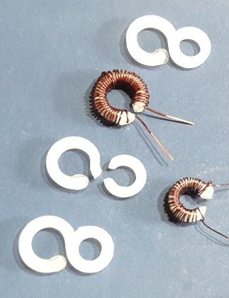
Os indutores do BPF eu enrolei em forma plastica (ar) com fio AWG 22,
usando formulas tradicionais. Os de 20 e 15m foram enrolados em uma
forma toroidal plastica, que tem o formato de um "8" usados para fixar
cortinas, cortei o '8" formando dois aneis com uma abertura , que
facilita o enrolamento.
The 250V PA capacitors must be made
of polyester.
The capacitors of the LPF filter must
be of silver mica or ceramic of 200V or more.
The BPF inductors I wrapped in
plastic (air) with AWG 22 wire, using traditional formulas. The 20 and
15m ones were wrapped in a plastic toroidal shape, which has the shape
of an "8" used to fix curtains, I cut the '8 "forming two rings with an
opening, which facilitates the winding.
Qualquer duvida no enrolamento ou material dos
indutores escrevam um Email.
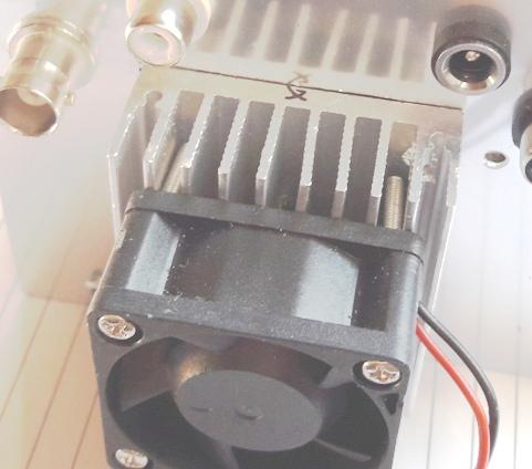
O IRF530 necessita de um dissipador, eu usei um de PC, com ventilador
(que acabei não precisando acionar o ventilador
até o
momento). O dissipador tem 45x45mm e 18mm de altura.
Any doubts in the winding or material
of the inductors write an Email.
The IRF530 needs a heatsink, I used a
PC, with a fan (I ended up not needing to start the fan so far). The
heatsink is 45x45mm and 18mm high.
Os capacitores CX15 e CX20 devem ser colocados no final da montagem e
ajustado seu valor em função da potencia e do
consumo de
corrente, os valores que estão no esquema foram para a minha
montagem.
Capacitors CX15 and CX20 must be
placed at the end of the building and adjusted their value according to
the power and current consumption, the values that are in the diagram
were for my assembly.
Ajustes :
O unico ajuste e do bias do IRF530, ajuste para 50mA até no
maximo 100mA.
Ajustar medindo a corrente de dreno sem sinal e jumpeando a
alimentação do bias (7805).
Outro ajuste mas operacional é do retardo no desligamento do
rele TX/RX (descrito acima).
Settings :
The only adjustment and the bias of
the IRF530, adjust to 50mA up to a maximum of 100mA.
Adjust by measuring the drain current
without signal and by skipping the bias supply (7805).
Another but operational adjustment is
the delay in turning off the TX / RX relay (described above).
Operação:
Com a alimentação de comando (12V) desligada a
operação é QRP.
Com a alimentação de comando ligada temos o
linear pronto
para operar.
A alimentação do dreno do PA deve ser de 12V a
25V para o
IRF5xx, já para os IRF6xx a
alimentação pode ser
de até 50V, com o cuidado de não ultrapassar 50W
de
potencia de saida (alterando a tensão de trabalho do capacitor
de 10µF).
Operation:
With the main supply (12V) off, the
operation is QRP.
With the main supply connected, the
linear is ready to operate.
The supply of the PA drain must be
from 12V to 25V for the IRF5xx, whereas for the IRF6xx the supply can
be up to 50V, taking care not to exceed 50W of output power (and the
10µF voltage).
XXXXXXXXXXXXXXXXXXXXXXXXXXXXX
Fizemos pequenas alterações para teste:
1. Colocamos um jumper removivel (tipo PC) para ajuste do bias do PA.
We made minor changes for testing:
1. We put a removable jumper (type
PC) to adjust the PA bias.
2. Adicionamos um circuito protetor do Mosfet do PA.
Para quem já montou transmissores com mosfet sabe o trabalho
de
trocar um mosfet, principalmente no desenvolvimento dos projetos.
2. We added a protective circuit for
the PA Mosfet.
For those who have already assembled
transmitters with a mosfet, you know the job of changing a mosfet,
especially in the development of projects.
O valor de R é de 0,47R de 3 a 5W.
Com este valor a interrupção da
alimentação
do Bias ocorre com cerca de 1,7A.
Com um Voltimetro medindo o valor da tensão sobre o resistor
de
0,47 podemos medir a corrente do dreno (0,47V =1A).
The R value is 0.47R from 3 to 5W.
With this value, the Bias power
interruption occurs at about 1.7A.
With a Voltimeter measuring the value
of the voltage on the resistor of 0.47, we can measure the drain
current (0.47V = 1A).
3. Colocamos tambem um circuito experimental para ajuste automatico do
bias do PA em função da temperatura. IMPORTANTE
coloque
um capacitor de 100nF em paralelo com os diodos.
3. We also put an experimental
circuit for automatic adjustment of the PA bias according to the
temperature. IMPORTANT place a 100nF capacitor in parallel with the
diodes.
Os diodos 1N4148 ao aquecer diminuem a tensão de bias. E
DEVEM
ser montados muito proximo do PA, com acoplador termico (pasta).
Devido ao não aquecimento do mosfet em
operação,
vamos retirar o circuito. Mas fica aqui a ideia !
The 1N4148 diodes on heating decrease
the bias voltage. AND MUST be mounted very close to the PA, with
thermal coupler (paste).
Due to the non-heating of the mosfet
in operation, we will remove the circuit. But here's the idea!
xxxxxxxxxxxxxxxxxxxxxxxxxxxxx
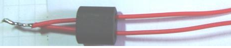
Como enrolar o binocular "focinho de porco"
1. Use 0,5m de fio flexivel isolado (encapado), corte ao
meio,
retire a isolação de duas pontas (2cm), junte as
pontas
sem isolação e solde. Passe pelo binocular com na
foto :
How to roll the binocular "pig nose"
1. Use 0.5m of flexible insulated
wire (capped), cut in half, remove the insulation from two ends (2cm),
join the ends without insulation and solder. Go through the binocular
like the picture:
deixando uma folga.
leaving a gap.
2. Passe cada fio pelo furo dando mais uma volta, serão
então duas voltas por fio (cada passagem do fio pelo furo
conta
uma volta). Deixe uma folga para facilitar, foto :
2. Pass each wire through the hole
giving one more turn, then there will be two turns per wire (each
passage of the wire through the hole counts one turn). Leave a gap to
make it easier, picture:
3. Novamente vamos passar cada fio retornando, ficaremos com 3 voltas
por fio. Deixando folga para facilitar a montagem. Foto :
3. Again we will pass each wire back, we will have 3 loops per wire.
Leaving a gap to facilitate assembly. Picture :

4. Aperte os fios e com ajuda de uma chave de fenda pequena
(relojoeiro) acerte os fios no furo e com um alicate de bico passe
outra volta para cada fio.
Corte os fios conforme necessário. Foto :
4. Tighten the wires and with the
help of a small screwdriver (watchmaker) fix the wires in the hole and
use a pliers to pass another turn for each wire. Cut the wires as
needed. Picture :
Como enrolar o choque de RF :
Enrole de 6 a 10 voltas de fio isolado com capa plastica. Corte
conforme necessidade. Foto :
How to wind the RF shock:
Wrap 6 to 10 turns of insulated wire
with plastic wrap. Cut as needed. Picture :
Como enrolar a bobina (ou transformador) bifilar ;
Usando dois fios isolados finos (rigido ou flexivel), preferencialmente
de duas cores. Passe de 4 a 6 vezes pelo furo (os
fios
podem ser torcidos ou não previamente) . Foto :
How to wind the bifilar (two wires) coil ( or transformer);
Using two thin insulated wires (rigid or flexible), preferably two
colors. Pass 4 to 6 times through the hole (the threads can be twisted
or not previously). Photograph :
Já enrolada (ready to finish)
:
Junte duas pontas dos fios de diferentes cores, sendo um do inicio e
outro do fim do enrolamento. Foto :
Join two ends of the wires of
different colors, one at the beginning and the other at the end of the
winding. Picture :
73 de py2ohh miguel