
JABUCA
Ladder filter – IF crystal filter
Photo of experimental filter (just with scrounged parts!)
There are a lot of receipts for designing crystal filters, we look a lot of Internet sites up about the designing and also schematics.
We didn't perform a lot of tests and experiments, leaving a door open for a possible improvement.
The main project was for a CW receiver, with a narrow passband of about 100Hz, centered on 800Hz. But we tested also a broader filter offering a possibility of hearing SSB and AM.
As a general way we can affirm the following rules:
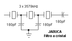
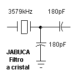
The circuit
Description
Speaking in a simple way, the crystal "resistance" on the resonance frequency is almost zero, while it has a very high "resistance" in any other frequencies. Putting two of them in series, this "resistance" effect is empowered and so on.
The inductive and capacitive reactance components cancel themselves at the resonant frequency in any resonant circuit, being it coil-capacitor (LC), crystal or ceramic resonator. The difference is in the way this reactance canceling happens as the pass band is broader when it is slower and the Q is also lower.
The crystals have a high Q, so the way the reactance canceling happens is abrupt (the ham who have a dipmeter can make a circuit short circuiting the crystal terminals and test).
Knowing that we come to the conclusion that in order to make a narrow CW filter it is necessary the crystals have a very close resonance between them (some 20Hz).
The one crystal option is for a multimode CW, SSB and AM receiver.
When narrower the pass band, bigger is the difficulty of exact tuning, but the selectivity and signal to noise ratio are bigger.
Parts list
With 3 crystals
03 3579 KHz HC49/U crystals (see text)
03 180pF silver plate or NP0 ceramic capacitors
01 20 x 25 mm unetched printed circuit board
With 1 crystal
01 3579 KHz HC49/U crystal
02 180pF silver plate or NP0 ceramic capacitors
01 12 x 12 mm unetched printed circuit board
Construction
with 01 crystal
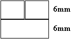
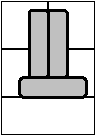
1. Cut the board
2. Solder the crystal


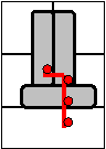
How to form the terminals to be soldered
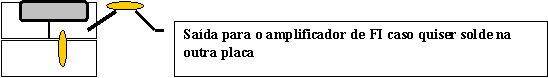
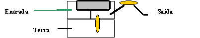
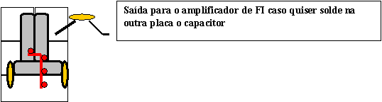
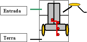
5. Inputs and outputs (Entradas e saídas)
With 03 crystals

2. Solder the crystals
5. Inputs and outputs (Entradas e saídas)
Tests and adjusts
JABUCA
Filtro de FI a cristal – ladder filter – IF crystal filter
Foto de filtro experimental (com sucata – mesmo !)
Existem muitas receitas para o projeto de filtros a cristal, consultamos muitos sites na Internet sobre projeto e também com esquemas.
Não fizemos muitos testes e experiências, deixando aberta uma lacuna com possibilidade de melhorias.
O projeto principal era de um receptor para CW, com um filtro com uma banda de passagem estreita da ordem de 100Hz, centrada em 800Hz. Mas testamos também um filtro mais largo dando possibilidade de ouvir SSB e AM.
De uma maneira geral podemos afirmar as seguintes regras :
O circuito
Descrição
Falando em uma linguagem muito simples, a "resistência" do cristal na freqüência de ressonância é praticamente zero enquanto que tem esta "resistência" muito elevada em outras freqüências . Colocando-se dois deles em série, esta "resistência" tem seu efeito dobrado e assim por diante.
Os componentes da reatância indutivos e capacitivos se anulam na freqüência de ressonância de qualquer circuito ressonante, seja ele bobina-capacitor, cristal ou ressonador cerâmico. A diferença esta na forma em que ocorre esta anulação de reatancias quanto mais lenta maior a banda de passagem e menor o Q.
Os cristais tem um Q elevado, a forma que ocorre a anulação das reatancias é abrupta (quem dispor de um ressonímetro pode fazer um elo curto-circuitando os terminais de um cristal e observar).
Sabendo disso concluímos que para um filtro agudo para CW é necessário que os cristais tenham uma ressonância muito próxima (dentro de 20Hz digamos).
A opção de se utilizar um só cristal é para um receptor multi-uso para CW, SSB e AM.
Quanto menor a faixa de passagem, maior a dificuldade de sintonia exata, mas maior será a seletividade e a relação sinal-ruído.
Lista de peças
Com 3 cristais
03 Cristais HC49/U de 3579 kHz (vide texto)
03 Capacitores de cerâmica NPO ou Plate de 180pF
01 placa de circuito impresso de 20 x 25 mm
Com 1 cristal
01 Cristais HC49/U de 3579 kHz
02 Capacitores de cerâmica NPO ou Plate de 180pF
01 placa de circuito impresso de 12 x 12 mm
Montagem
Com 01 cristal
1. Cortar placa
2. Soldar o cristal
Como dobrar os lides para a solda
5. Entradas e saídas
Com 03 cristais
2. Soldar os cristais
5. Entradas e saídas
Testes e ajustes