JABUCA
Front end filter – band pass
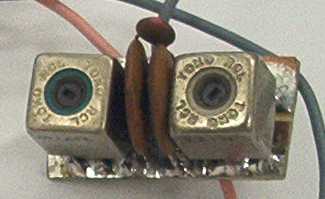
Front end of the JABUCA
The circuit chosen to be the input filter is easy and works very well.
The only difficulty is the Toko 10mm RF FM/TV transformers procurement, the ones I have were scrounged from old TVs. They are possible to be found in TV repairing-service shops.
Other transformers like the 10,7 MHz FM IF ones can be used. Or even other former types with a primary wound for some 5µH and the secondary with a turns ratio of 5:1.
The circuit
Description
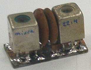
The circuit is a very traditional in QRPs and it uses a transformer in the antenna input that raises the antenna impedance by the inter-turns square ratio of 22:4, that is, 22/4 = 5.5 and 5.5x5.5 = 30.25 times so the antenna impedance is raised to 50 Ohms x 30.25 = 1512 Ohms to raise the tuned circuit Q with the 120pf capacitor..
The capacitive coupling between both transformers must be weak in order to not to affect the Q, the best would be a value around 8.2 pF, that showed a higher Q but a very big attenuation too, we tweaked the value till getting a good compromise between passband (Q) and gain (attenuation), arriving to the 18pF value.
The second transformer does the inverse work, that is, it turns our 1512 Ohms to 50 Ohms, which is the inpunt impedance to the TA7358 pin 1.
Parts list
2 IF Transformers – see text
2 120 pF ceramic capacitors
1 18 pF ceramic capacitor
1 15 mm by 30 mm unetched pcb
Construction
Transformers :
Coil sketch
Open the transformer shielding with care, forcing the sides, the shielding ends a bit damaged usually.
Retire the inner coil, unwind the fixation taking off wax and the wires.
Wind 22 turns uniformly distributed, with a wire thinner than 0.15mm, laying 5 turns in the first channel, 6 turns in the second channel, 6 turns in the third channel and 5 turns in the fourth channel.
You must follow the same turn direction and taking care for the winding starts stay in the same side in order to make easy the fixation (the starts will be connected to earth and must be in the same phasing), wind 4 turns of the same wire with a turn per channel.
The wire tips must be hold with a fine (#220) bent sandpaper, and the wire pushed to remove the enamel, then wind in the base pin (attention to the winding starts) and solder.
Circuit

The winding starts are connected to earth, make sure
before winding the transformers!ADJUSTMENTS
Connect the antenna to the side it will be connected finally and the receiver side to an existing receiver (for ham band) and tweak for best signal!
In the case the core(s) be out of the shielding(s) raise the 120pF capacitor value or put another capacitor in parallel, the core must be inside the coil or almost inside.
Another sketch for another transformer type that can be used.

this type of transformer is used as IF in FM radios
Links about this subject:
http://www.intio.or.jp/jf10zl/ozlcoil.htm Our friend Kazu shows how to wind inductors in IF transformers.
http://www.g4wif.fsnet.co.uk/q_tech1.htm Here George G3RVJ show us how to build pass band filters with commercial Toko transformers.
Good luck!
JABUCA
Filtro de entrada – band pass – front end
Front end do JABUCA
O circuito escolhido para ser utilizado no filtro de entrada, é prático e funciona muito bem.
O único inconveniente é a obtenção dos transformadores de RF FM/TV de 10mm da Toko, os que eu possuo foram retirados de TVs sucateados. Mas ainda são possíveis de se encontrar em oficinas de reparo de TV.
Outros trafos como os de FI FM de 10,7 MHz podem ser utilizados. Ou ainda outros tipos com núcleo ajustavel sendo o primário enrolado para cerca de 5µH e o secundário com uma relação de espiras de 5:1.
O circuito
Descrição
O circuito é muito tradicional em QRPs e utiliza um transformador na entrada de antena que eleva a impedância de antena na razão do quadrado da relação inter-espiras de 22:4 ou seja 22/4 =5,5 e 5,5x5,5 =30,25 vezes ainda impedância de antena 50 Ohms x 30,25 = 1512 Ohms para aumentar o Q do circuito sintonizado em conjunto com o capacitor de 120pF.
O acoplamento capacitivo entre os transformadores deve ser fraco para não afetar o Q, o ideal seria valores ao redor de 8,2pF, que apresentavam um Q elevado mas uma atenuação muito grande, alteramos o valor até obter um resultado bom entre banda passante (Q) e ganho (atenuação) chegamos ao valor de 18pF.
O segundo transformador faz o inverso ou seja transforma nossos 1512 Ohms de impedância em 50 Ohms, que é a impedância de entrada no pino 1 do TA7358.
Lista de peças
2 Transformadores de FI – veja texto
2 capacitores de 120 pF cerâmico
1 capacitor de 18 pF cerâmico
1 placa virgem para circuito impresso de 15 mm por 30mm
Montagem
Transformadores :
Esboço das bobinas
Abrir a blindagem dos transformadores com cuidado, forçando as laterais, a blindagem normalmente fica um pouco avariada.
Retire a bobina interna, desenrole a fiação eliminando cera e os fios.
Enrole 22 voltas distribuídas uniformemente, de fio com diâmetro inferior a 0,15mm, sendo 5 voltas no primeiro canal, 6 voltas no segundo canal, 6 no terceiro canal e 5 no quarto canal.
A seguir no mesmo sentido e tendo o cuidado que os inícios de enrolamento fiquem do mesmo lado para facilitar a fiação (os inícios serão ligados a terra e deverão ter a mesma fase), enrole 4 voltas do mesmo fio sendo uma volta em cada canal.
As pontas dos fios devem ser seguras com uma lixa fina (#220) dobrada, e o fio puxado devagar para remover o verniz, enrole no pino da base (atenção aos inícios de enrolamento) e solde.
Circuito
Os inícios dos enrolamentos estão ligados a terra, observe
antes de enrolar os transformadores !AJUSTES
Ligue a antena do lado que ela será ligada e o lado receptor a um receptor comercial (para radioamadores) ajuste para o máximo sinal !
Caso o(s) núcleo(s) fique(m) para fora aumente o valor dos capacitores de 120pF ou coloque outro capacitor em paralelo, o núcleo deverá ficar dentro da bobina ou quase dentro ( aprova de chacoalhos...
Ilustração de outro tipo de Transformador que pode ser utilizado
este tipo de transformador é utilizado como FI de rádios FM
Links que tratam deste assunto :
http://www.intio.or.jp/jf10zl/ozlcoil.htm Nosso amigo Kazu ensina como enrolar indutores a partir de trafos de FI.
Boa sorte !