Tests with the 74HC240
The IC 74HC240 was initially used in transmitters by the american ham N7KSB, who built versions for 10m (0.9W), 15m and 20m (0.5W) and with a vertical ground plane antenna worked more than 30 countries and all the continents. See the link to:
http://www.madisoncounty.net/~kj5tf/n7ksb.html
Other ham using them was K0JD, who uses the 74HC240 as a buffer for VFOs, he also mentions the use of the 74HC04 and the 74AC04.
http://www.seboldt.net/k0jd/hcbuffer.html
The 74HC240 is an 8 bit inverter buffer in origin, so it has 8 inverter gates enabled by groups of 4 (2 enables). The nominal working voltage is 5 Volts, though most people makes it work at 8 Volts in order to increase the power.
Another example is the famous Christmas Cracker, a 40m 1/2W transceiver using the 74HC240 as VFO - buffer - PA and driver for the balanced diode receiver mixer, built by G3CWI. See in:
http://www.qsl.net/g3cwi/christma.html
Another implementation is in german in the site:
http://www.ardf.ch/Technik/Tx_80m.htmA very good work can be seen in the NorCal 38 SPECIAL 30m transceiver, where the 74HC240 is the transmitter PA, see it in:
Schematic in
http://www.norcalqrp.com/kits/38spcl/38sch.htmlSpecifications in
http://www.norcalqrp.com/kits/38spcl/38spcl.htmParts list in
http://www.norcalqrp.com/kits/38spcl/parts.htmlOur friend Gomes PY2MG already drew a VFO-Buffer with the 74HC240 in an AM 10W TX in:
http://www.qsl.net/py2mg/Images/LU8EHA_TX.PDF
The LU8EHA original work is in:
We have another (cuban) version of the N7KSB work in:
http://www.radiohc.org/Distributions/Dxers/ultra-simple-transmitter.html
Finally 4S7NR drew more informs about the 74HC240 application in:
http://www.qsl.net/qrp/tx/logi-tx.htm
NOTES
It is important yet to mention that the 74HC240 can drive directly an IRF510 FET transistor being able to give until 10W. Another application is using it to drive a balanced diode mixer, which needs a considerable power drive, easily supplied by a 74HC240 gate.
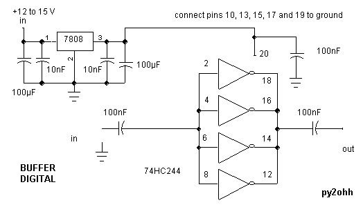
We did some tests with a Philips 74HC240, with a cost of almost R$1.00 (U$0.30 in sept/2003), we use also the 74HCT240 with the same results, we also used a 74HC244 (SMD) as a buffer because it does not work as oscillator (it is not an inverter gate, but it has the same pin numeration as the 240), and the tests with the 74F240 showed this type does not work in this conditions!
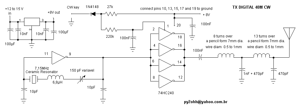
Another important fact is that each gate output impedance is about 16 Ohms, that is, connecting 4 in parallel we will have around 4 Ohms output, the matching is usually done with a low pass tuner with a low Q (around 1) or even with broad band transformers or trifilar coils.
The digital oscillators generate square waves which are not proper for transmitting and most of the mixer, but filtering them with low pass filters we get rid of the harmonics (for the one who does not know: the square waves are formed by the combination of a wave with its odd harmonics = getting rid of the harmonics we get the desired senoidal wave).
Another interesting fact is the use of EXCLUSIVE-OR - XOR as mixer for square waves, easing its use in super heterodyne receivers and the known universal VFOs. For the one who likes experimenting, this work with digital signals was always scarcely explored.
A fact to be considered is the showing up of transmission CLICs (in CW), but it was not our case.
We recommend the building using the dead bug method, which eases the building a lot because it is simple and makes possible using SMD parts.
Our tests :
We built this project in about 3 hours and by the end of the tests we got a QSO with Rio de Janeiro, with 0.3W getting a 579. The construction was done by the dead bug method and the rig was stuck (using thermal conductor goo) on an aluminum board, serving as a heat sink and increases the mechanic stiffness of the rig.
The coils were made using a pencil as a former and the wire diameter (as long as it stands rigid and self-supported) does not matter - but the length of winding does and must be adjusted for the better output signal.
Schematic:

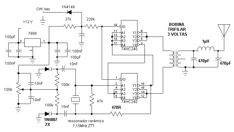
2. An 74HCT240 oscillator and buffer-PA for its use in transmitter, in this project we made possible the use of varicap diodes with ceramic resonators. To increase the output impedance we chose to work in push-pull with 3 by 3 gates, note we use an additional inverter in one side, driving a trifilar coil raising the impedance by 4 times, ending close to 48 Ohms.
Schematic:

Schematic :

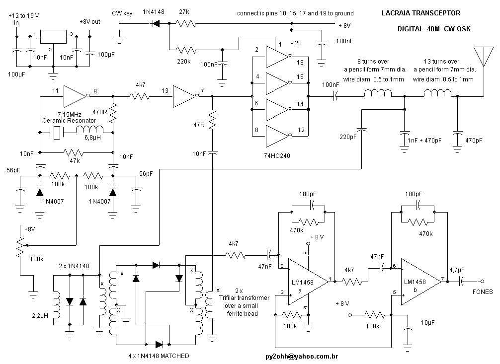
Schematic:

In all the built and tested projects, we note that when the impedances are correctly adjusted (or almost there) the IC heats very little and even powered with 8 V the IC does not show a lot of heating.
We even used the SMD package and the heating was not exaggerate.
Used as an oscillator it presents a stability similar to conventional VXO circuits.
An inverter gate was enough to drive a double balanced diode mixer if it was powered between 6 and 8 V and the impedances were correctly matched.
Testes com 74HC240
O CI 74HC240 foi inicialmente utilizado em transmissores pelo radioamador americano N7KSB, que construiu versões para 10m (0,9W), 15m e 20m (0,5W) e com uma antena vertical plano terra conseguiu trabalhar mais de 30 países e todos os continentes. Veja o link em :
http://www.madisoncounty.net/~kj5tf/n7ksb.html
Outro radioamador a utiliza-los foi K0JD, onde emprega o 74HC240 como Buffer para VFOs, também menciona o uso do 74HC04 e do 74AC04.
http://www.seboldt.net/k0jd/hcbuffer.html
Originalmente o 74HC240 é um buffer inversor de 8 bits, possuindo portanto 8 portas inversoras acionadas (enable) 4 a 4 (2 acionamentos). A tensão nominal de trabalho é de 5 Volts apesar que a maioria, para aumentar a potência, trabalha até com 8 Volts.
Outro exemplo é o famoso Christmas Cracker um transceptor de 40m , 1/2W utilizando o 74HC240 como VFO - buffer - PA - e excitador para o mixer do receptor a diodo balanceado, montado por G3CWI. Veja em :
http://www.qsl.net/g3cwi/christma.html
Outra montagem aparece em alemão no site :
http://www.ardf.ch/Technik/Tx_80m.htm
Um trabalho muito bom pode ser observado no transceptor para 30m o 38 SPECIAL da Norcal, onde o 74HC240 faz o transmissor veja em :
Esquema em
http://www.norcalqrp.com/kits/38spcl/38sch.htmlEspecificações em
http://www.norcalqrp.com/kits/38spcl//38spcl.htmLista de componentes em
http://www.norcalqrp.com/kits/38spcl/parts.htmlJá o nosso colega Gomes PY2MG traz um VFO- Buffer com o 74HC240 em um TX AM de 10W em :
http://www.qsl.net/py2mg/Images/LU8EHA_TX.PDF
O original de LU8EHA está em :
Temos outra versão (cubana) do trabalho do N7KSB em:
http://www.radiohc.org/Distributions/Dxers/ultra-simple-transmitter.html
Ainda 4S7NR traz mais informações sobre a aplicação do 74HC240 em:
http://www.qsl.net/qrp/tx/logi-tx.htm
NOTAS
Importante ainda citar que o 74HC240 pode acionar diretamente um transistor FET IRF510 podendo render até 10W. Outra aplicação é o uso para acionamento de mixer a diodo balanceados que exigem uma potência considerável para funcionar, o que uma porta do 74HC240 pode suprir facilmente.
Fizemos alguns testes com o 74HC240 da Philips, que esta custando cerca de R$1,00 (U$0,30 em set/2003), utilizamos também o 74HCT240 com os mesmos resultados, também utilizamos um 74HC244 (SMD) como buffer pois não funciona como oscilador (não é porta inversora, mas tem a mesma numeração de pinos do 240), já os testes com o 74F240, mostraram que este tipo não trabalha nestas condições !
Outro fato importante é que a impedância de saída para cada porta esta em torno de 16 Ohms ou seja ligando-se 4 em paralelo teremos em torno de 4 Ohms de saída, a compensação normalmente é feita por um acoplador passa baixa com um Q baixo (em torno de 1) ou então com transformadores broad band ou bobinas trifilares.
Os osciladores digitais produzem ondas quadradas que não são apropriadas para a transmissão e para a maioria dos mixers, mas filtrando-a com filtros passa baixa eliminamos as harmônicas (para quem não sabe : as ondas quadradas são originadas pela soma de uma onda com suas harmônicas impares = eliminando as harmônicas isolamos a onda senoidal desejada).
Outro fato interessante é o uso de portas OU-EXCLUSIVO - XOR como mixer para ondas quadradas, facilitando o uso para receptores super heterodinos e para os conhecidos VFOs universais. Para quem gosta de experimentar, este trabalho com sinais digitais foi sempre pouco explorado.
Um fato a ser considerado é o aparecimento de CLICS de transmissão (em CW), que não foi o nosso caso.
Recomendamos a construção pelo método dead bug, que facilita muito a montagem, que já é simples e viabiliza a utilização de componentes SMD.
Nossos testes :
Realizamos este projeto em cerca de 3 horas e no final dos testes conseguimos um QSO com o Rio de Janeiro, com 0,3W recebendo 579 . A construção foi feita pelo método dead bug e o conjunto foi aparafusado (lambuzado com pasta térmica) em uma placa de alumínio, que serve de dissipador e aumenta a rigidez mecânica do conjunto.
As bobinas foram feitas utilizando-se um lápis como forma e o diâmetro do fio (contanto que fique auto-suportada e rígida) não importa - sim o comprimento do enrolamento que deve ser ajustado para um melhor sinal de saída.
Esquema:

2. Projeto de um oscilador e um buffer-PA com um 74HCT240 para o uso em transmissores , neste projeto conseguimos viabilizar o uso de varicap com os ressonadores cerâmicos. Para aumentar a impedância de saída optamos por trabalhar em push-pull com 3 por 3 portas, note que utilizamos um inversor a mais em um dos lados, acionando uma bobina trifilar que aumenta a impedância em 4 vezes, resultando cerca de 48 Ohms.
Esquema :

praticamente igual ao do encapsulamento DIP.
Esquema :

Esquema

Em todos os projetos montados e testados, notamos que quando as impedâncias estão corretamente ajustadas ( ou o mais próximo disso) o CI aquece muito pouco e mesmo alimentado com 8 V o CI não apresenta muito aquecimento.
Mesmo ao utilizarmos encapsulamento SMD o aquecimento não foi exagerado.
Utilizado como oscilador ele apresenta uma estabilidade semelhante ao circuito de VXO convencional.
Uma porta inversora se mostrou suficiente para excitar um mixer a diodos duplamente balanceados, desde que alimentada entre 6 a 8 V e as impedancias corretamente ajustadas.