GERADOR
DE ONDAS E VFO
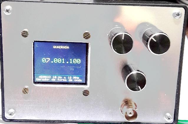
Montamos em uma caixa patola com uma nova tampa - painel de aluminio
Ola amigos ...vamos descrever um gerador de ondas quadradas,
triangulares e senoidais com o ARDUINO NANO e o modulo DDS AD9833. E de
quebra teremos tambem um VFO até 12 MHz.
Este projeto foi baseado no seguinte link :
LINK
para a pagina do John
Fizemos algumas modificações em hardware e em software
como adaptar para funcionar como VFO, adicionar amplificador de RF e de
AF e mais algumas pequenas alterações.
Bugs e alguns problemas podem aparecer pois alterei o programa e
não sou expert neste assunto sou apenas um curioso !
Como o modulo DDS AD9833 é pequeno (15x20mm) e gera
frequencias e sinais com precisão, elegi como um equipamento
facil de montar e com muitos recursos. E principalmente por ser um
otimo VFO até 12MHz.
O circuito :
Funcionamento :
O processamento de dados é feito pelo arduino nano, a interface
de entrada de dados é feita pelos dois encoders um seleciona a
casa decimal (a cor da casa
decimal selecionada muda de verde para amarelo) e se apertado
para acionar a chave interna ele muda a forma de onda (mostrada no
display). O outro encoder altera a casa decimal (frequencia) para cima
ou para baixo e sua chave não tem função.
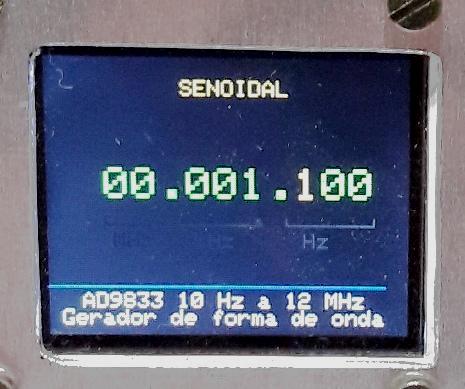
Foto : Gerador setado para onda senoide o cursor de
alteração numérica, em amarelo, esta na centena da
unidade
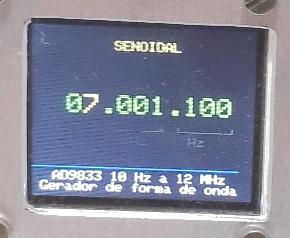
Foto : Cursor esta na unidade do milhão
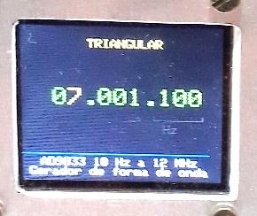
Foto: gerando
onda de forma triangular
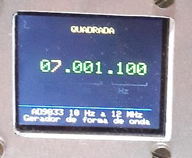
Foto: gerando onda de forma quadrada
O arduino conversa com o AD9833 e com o display com uma
comunicação serial ...note que as conexões de data
e clock tem conexão comum, o arduino quando quer enviar um dado
ao display aciona a entrada CS (Chip Select) ou seja seleciona que
é para este dispositivo que vão os comandos.
Após setar a frequencia desejada o arduino envia os dados
ao AD9833 que vai gerar a forma de onda e a frequencia setadas enviado
este sinal pela saida ... se a frequencia for abaixo de 1MHz ...o sinal
vai para o LM386 ... que tem um trimpot na entrada que serve para
limitar o sinal para que não aja saturação ou
deformação. Já potenciometro na saida, que vai no
painel controla o nivel de saida do LM386 ou de audio. Ao passar de
1MHz o arduino envia um sinal a porta D4 de 5V que aciona o transistor
que por sua vez atua o rele, mudando o LM386 para um filtro passa
baixas de 13,5MHz e depois para um amplificador de RF. A sida de sinal
em AF ou RF é no mesmo ponto, chaveada pelo rele.
Material :
Compramos a maioria dos componentes na China via Ebay :
Arduino nano U$2.5
Display com ST7735 de driver
U$4 tem dois modelos.. veja as fotos ..o modelo "QDTech" exige a
troca de library este
display é de 128x160 1/8" SPI serial TFT.
Para identificar o display correto é necessario ver fotos, da
parte trazeira com atenção, pois os chineses anunciam uma
coisa e vendem outra.
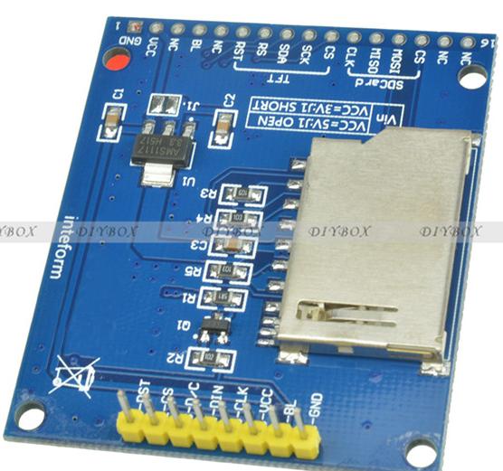
Foto : display QDTech funciona mas não recomendo
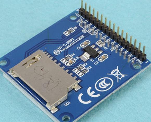
Foto display recomendado (possui uma linha apenas de terminais
pretos)
Encoder com chave U$1
Ad9833 DDS modulo U$6
Duvidas e ajuda escreva para py2ohhZZZyahoo.com.br (ZZZ =@)
Fotos da montagem
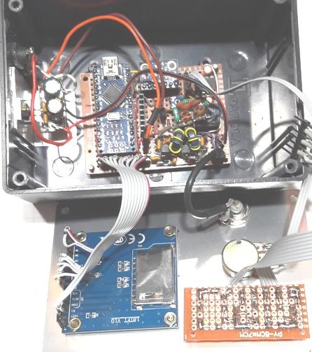
Foto : caixa patola interno da esquerda para direita fonte de 5V,
arduino nano, AD9833 dds e LM386, rele com o filtro LPF (capacitores
ceramicos) e embaxo o amplificador de RF.
Na tampa temos o display , potenciometro e a placa em que soldamos os
encoders.
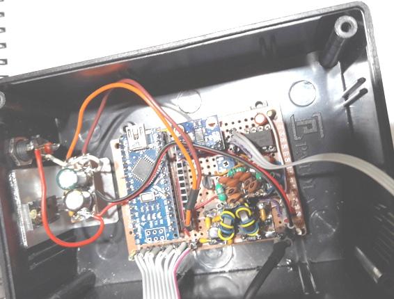
Foto : detalhe da parte interna da caixa patola.
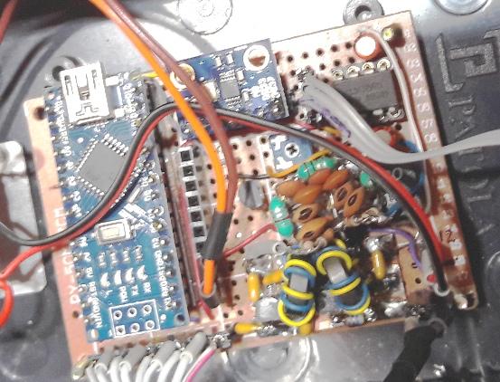
Foto : com maior detalhe
Video da montagem
VIDEO POSTADO NO YOUTUBE CANAL
PY2OHH
Arquivo .INO para download
Sketch do arduino (programa)
/*
AD9833 Waveform Module vwlowen.co.uk
modificado por py2ohh miguel sept 2016
*/
#include <SPI.h>
#include
<Rotary.h>
// Rotary encoder: https://github.com/brianlow/Rotary
#define dc
8
//era A0 Define pins for TFT
display.
#define cs
9
// era a1 10
#define rst
12
//era 9 a2
#include <Adafruit_GFX.h> // Core
graphics library
// include Adafruit library OR QDTech library depending on the
display's controller chip.
#include
<Adafruit_ST7735.h>
// Hardware-specific library
Adafruit_ST7735 tft = Adafruit_ST7735(cs, dc, rst);
// #include
<Adafruit_QDTech.h>
// Hardware-specific library
//Adafruit_QDTech tft = Adafruit_QDTech(cs, dc, rst);
// https://github.com/zigwart/Adafruit_QDTech
#define BLACK
0x000
// Define the display colours we'll be using
#define BLUE
0x001F
// so they're constants regardless of which
#define GREEN
0x07E0
// display library we use.
#define YELLOW 0xFFE0
#define GREY 0x632C
#define BRANCO 0xFFFF
const int SINE =
0x2000;
// Define AD9833's waveform register value.
const int SQUARE =
0x2020;
// When we update the frequency, we need to
const int TRIANGLE =
0x2002;
// define the waveform when we end writing.
int wave = 0;
int waveType = SINE;
int wavePin = 7;
int freqUpPin =
2;
// Define rotary encoder pins.
int freqDownPin = 3;
int stepUpPin = 5;
int stepDownPin = 6;
int rfPin =4;
const float refFreq =
25000000.0;
// On-board crystal reference frequency
const int FSYNC =
10;
//era 10 Standard SPI pins for the AD9833 waveform generator.
const int CLK =
13;
// CLK and DATA pins are shared with the TFT display.
const int DATA = 11;
Rotary r = Rotary(freqUpPin, freqDownPin); // Rotary
encoder for frequency connects to interrupt pins
Rotary i = Rotary(stepUpPin, stepDownPin); // Rotart
encoder for setting increment.
unsigned long freq =
1000;
// Set initial frequency.
unsigned long freqOld = freq;
unsigned long incr = 1;
unsigned long oldIncr = 1;
void setup() {
pinMode(freqUpPin, INPUT_PULLUP);
// Set pins for rotary encoders as INPUTS and enable
pinMode(freqDownPin, INPUT_PULLUP); //
internal pullup resistors.
pinMode(stepUpPin, INPUT_PULLUP);
pinMode(stepDownPin, INPUT_PULLUP);
pinMode(wavePin, INPUT_PULLUP);
pinMode(rfPin, OUTPUT);
// Can't set SPI MODE here because the display and the
AD9833 use different MODES.
SPI.begin();
delay(50);
// Initialize either Adafruit OR QDTech display
//QDTech display
// tft.init();
//Adafruit display
tft.initR(INITR_BLACKTAB); // initialize a ST7735S
chip, black tab
tft.setRotation(3);
tft.setTextWrap(false);
// Allow text to run off right edge
tft.fillScreen(BLACK);
tft.drawFastVLine(25, tft.height()-55, 4,
GREY); // Display
'static' cosmetic text.
tft.drawFastVLine(50, tft.height()-55, 4, GREY);
tft.drawFastVLine(58, tft.height()-55, 4, GREY);
tft.drawFastVLine(93, tft.height()-55, 4, GREY);
tft.drawFastVLine(105, tft.height()-55, 4, GREY);
tft.drawFastVLine(144, tft.height()-55, 4, GREY);
tft.drawFastHLine(25, tft.height()-52, 25, GREY);
tft.drawFastHLine(58, tft.height()-52, 37, GREY);
tft.drawFastHLine(105, tft.height()-52, 40, GREY);
tft.setTextColor(GREY);
tft.setCursor(23, tft.height()-48);
tft.print(" MHz kHz Hz");
tft.setCursor(15, tft.height() -20);
tft.setTextSize(1);
tft.drawFastHLine(0, tft.height() - 23, tft.width()-10, BLUE);
tft.setTextColor(BRANCO);
tft.println("AD9833 10 Hz a 12 MHz ");
tft.print(" Gerador de forma de onda");
// Configure interrupt for rotary encoder and enable.
PCICR |= (1 << PCIE2);
PCMSK2 |= (1 << PCINT18) | (1 << PCINT19);
sei();
AD9833reset();
// Reset AD9833 module after power-up.
delay(50);
AD9833setFrequency(freq,
SINE);
// Set the frequency and Sine Wave output
updateDisplay();
}
void updateDisplay() {
// To complicate things, the display uses SPI MODE0 but the
AD9833 uses SPI MODE3 so it's
// necessary to switch modes before each SPI transfer.
SPI.setDataMode(SPI_MODE0);
tft.fillRect(50, 10, 100, 12,
BLACK);
// Clear text.
tft.setTextColor(YELLOW);
tft.setCursor(47, 10);
tft.setTextSize(1);
switch (waveType) {
case SINE: tft.print(" SENOIDAL "); break;
case SQUARE: tft.print(" QUADRADA "); break;
case TRIANGLE: tft.print(" TRIANGULAR"); break;
}
tft.fillRect(25, 50, 140, 14,
BLACK); //
Clear frequency numerals.
tft.setTextColor(GREEN);
tft.setTextSize(2);
tft.setCursor(25, 50);
format(freq);
// Show frequency in formatted form.
}
void format(unsigned long value) {
// Break the frequency value down into individual digits
& into variable 'digit'.
// If a digit corresponds with the currently-selected x10
increment, change the
// text colour to YELLOW. All other digits and commas are
GREEN.
unsigned long j = 10000000; //era 1000000
for (int i=7; i>=0; i--) {
int digit = (value / j) % 10;
incr == j ? tft.setTextColor(YELLOW):
tft.setTextColor(GREEN);
tft.print(digit);
if ( (i == 6) || (i == 3))
{
// Add commas at millions and thousands
tft.setTextColor(GREEN);
tft.print(".");
}
j /= 10;
}
}
void loop() {
if (oldIncr != incr) {
updateDisplay();
oldIncr= incr;
}
// Check 'increment' rotary encoder. Increase or decrease
'increment' by a factor of x10
// if encoder has been turned.
unsigned char result = i.process();
if (result) {
if (result == DIR_CW) {if (incr < 1000000)
incr *= 10;}
if (result == DIR_CCW) {if (incr >= 10) incr /=
10;}
updateDisplay();
}
if (freq > 1000000) {
digitalWrite(rfPin, HIGH);
}
else {
digitalWrite(rfPin, LOW);
}
// Check if push button on 'increment' rotary encoder is pushed
and set Wave Type accordingly.
if (digitalRead(wavePin) == LOW) {
wave += 1;
if (wave > 2) wave = 0;
switch (wave) {
case 0: waveType = SINE; break;
case 1: waveType = SQUARE; break;
case 2: waveType= TRIANGLE; break;
}
AD9833setFrequency(freq,
waveType); // Set AD9833 to frequency and
selected wave type.
updateDisplay();
delay(200);
}
if (freq != freqOld)
{
// If frequency has changed, interrupt rotary encoder
AD9833setFrequency(freq,
waveType); // must have been turned so update
AD9833 and display.
updateDisplay();
freqOld =
freq;
// Remember new frequency to avoid unwanted display
}
// and AD9833 updates.
}
// AD9833 documentation advises a 'Reset' on first applying power.
void AD9833reset() {
WriteRegister(0x100); // Write '1' to AD9833 Control
register bit D8.
delay(10);
}
// Set the frequency and waveform registers in the AD9833.
void AD9833setFrequency(long frequency, int Waveform) {
long FreqWord = (frequency * pow(2, 28)) / refFreq;
int MSB = (int)((FreqWord & 0xFFFC000) >>
14); //Only lower 14 bits are used for data
int LSB = (int)(FreqWord & 0x3FFF);
//Set control bits 15 ande 14 to 0 and 1, respectively, for
frequency register 0
LSB |= 0x4000;
MSB |= 0x4000;
WriteRegister(0x2100);
WriteRegister(LSB);
// Write lower 16 bits to AD9833 registers
WriteRegister(MSB);
// Write upper 16 bits to AD9833 registers.
WriteRegister(0xC000);
// Phase register
WriteRegister(Waveform);
// Exit & Reset to SINE, SQUARE or TRIANGLE
}
void WriteRegister(int dat) {
// Display and AD9833 use different SPI MODES so it has to be
set for the AD9833 here.
SPI.setDataMode(SPI_MODE2);
digitalWrite(FSYNC,
LOW); //
Set FSYNC low before writing to AD9833 registers
delayMicroseconds(10);
// Give AD9833 time to get ready to receive data.
SPI.transfer(highByte(dat));
// Each AD9833 register is 32 bits wide and each 16
SPI.transfer(lowByte(dat));
// bits has to be transferred as 2 x 8-bit bytes.
digitalWrite(FSYNC,
HIGH); //Write
done. Set FSYNC high
}
// Interrupt service routine for the 'frequency' rotary encoder.
ISR(PCINT2_vect) {
unsigned char result = r.process();
if (result) {
if (result == DIR_CW)
{
// Clockwise rotation so add increment to frequency
if ((freq + incr) < 12000000)
freq+=incr; //era 6000000
} else {
if (freq > incr)
{
// Counter-clockwise rotation so subtract increment
freq -=
incr;
// from frequency unless it would result in a negative
} else
{
// number.
if (freq >=
1) incr /= 10;
if (incr < 1)
incr =
1;
// Compensate for math rounding error.
}
}
}
}
++++++++++++++++++++++++++++++++++++
73 de py2ohh miguel