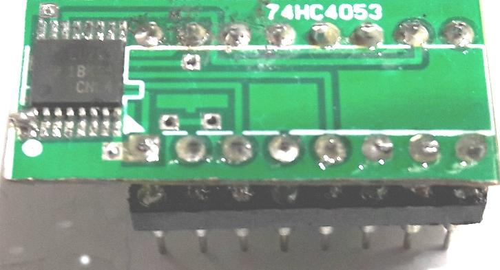
PCB
adaptadora para usar o FST3253 TSSOP no lugar do 74HC4053
Adapter PCB to use the FST3253 TSSOP
in place of the 74HC4053
Em algumas PCBs temos uma PCB adaptadora.
EX . Dual band PCB
On some PCBs we have an adapter PCB.
EX. Dual band PCB
No detalhe
in detail
Vamos descrever como montar esta plaquinha adaptadora:
Precisaremos de um soquete DIP 16 pinos torneados
1. Soldar o FST3253 TSSOP ou SN74CBT3253Dxx, atenção ao
pino 1.
Os metodos de soldagem que uso são :
a. Soldar pino a pino com um fio de cobre fino enrolado na ponta do
soldador.
b. Com pasta especial de soldagem.
c. Soldado os pinos juntos e curto e sugando com sugador de solda e com
cordoalha de cabo coaxial.
2. Testar para verificar se os pinos não estão em curto,
observando a tabela abaixo.
Testar um a um os pontos de conexão
HC4053 3253
1 > 13
2
> 10
3
> 12
4
> NC
5
> 11
6
> GND
7
> GND
8
> GND
9
> 2
10
> 14
11
> GND
12
> GND
13
> GND
14
> GND
15
> 9
16
> 16
Pinos 1, 8 e 15 do 3253 são ligados ao terra (GND).
Obs. dependendo do fabricante os pinos 1 e 15 que são "ENABLE"
ou ativadores das portas, podem ter outro tipo de conexão ou
seja desligados e não aterrados.
Em algumas placas antigas, o pino 1 não esta aterrado ...
dependendo do fabricante deve ser ligado a terra.
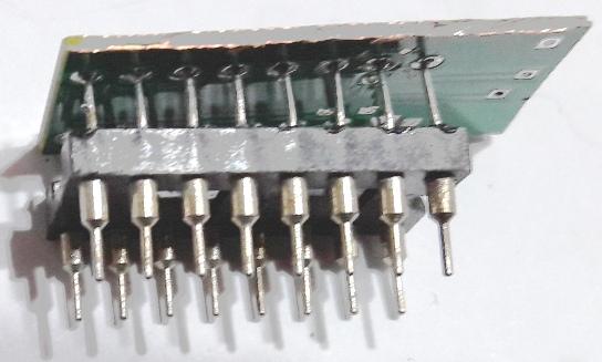
3. Devemos soldar em todos os pinos, do soquete com pinos torneados, um
lide rigido ou um fio de sobra
de componentes.
4. Cuidado ao soldar pois os fios deverão passar pelos furos da
PCB
5. Soldar a PCB ao soquete, mantendo os fios curtos.
We will describe how to mount this
adapter plate:
We will need a turned 16 pin
DIP socket
1. Solder the FST3253 TSSOP or
SN74CBT3253Dxx, pay attention to pin 1.
The welding methods I use are:
a. Solder pin to pin with a thin
copper wire wound around the end of the welder.
b. With special soldering paste.
c. Solder the pins together and short
and sucking with solder sucker and with coaxial cable strand.
2. Test to verify that the pins are
not shorted, observing the table below.
Test the connection points one by one
HC4053 3253
1 > 13
2 > 10
3 > 12
4 > NC
5 > 11
6 > GND
7 > GND
8 > GND
9 > 2
10 > 14
11 > GND
12 > GND
13 > GND
14 > GND
15 > 9
16 > 16
Pins 1, 8 and 15 of the 3253 are
connected to ground (GND).
Note depending on the manufacturer,
pins 1 and 15, which are "ENABLE" or port enablers, may have another
type of connection, that is, turned off and not grounded.
On some older boards, pin 1 is not
grounded... depending on the manufacturer it must be grounded.
3. We must solder on all pins, from
the socket with turned pins, a rigid lead or a spare wire from
components.
4. Be careful when soldering as the
wires must pass through the holes in the PCB
5. Solder the PCB to the socket,
keeping the wires short.
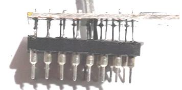
Esta PCB não tinha o pino 1 ligado ao terra, tivemos que
conectar.
This PCB didn't have pin 1 connected
to ground, we had to connect it.
73 de py2ohh miguel