ARDUINO VFO DE 50kHz CW 40m
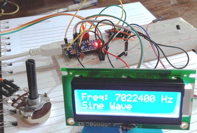
Aqui descreveremos um VFO super simples, pequeno e barato, usa o
AD9833, que custa cerca de 4U$, um potenciometro linear para ajuste e
um display LCD 16x2 comum.
Não achei ele muito bom, pois fica nuito limitado, com um
encoder ele teria maiores
utilidades.
Mas estou descrevendo para os que gostam de arduino e RF possam estudar
o programa.
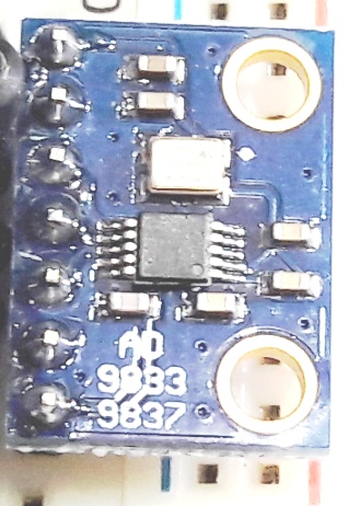
Modulo AD9833 com 13x18mm tem um tamanho pequeno.
Sketch :
/*
AD9833 DDS Waveform Generator by Glen Popiel - KW5GP
This program is free software: you can redistribute it and/or
modify
it under the terms of the version 3 GNU General Public License as
published by the Free Software Foundation.
This program is distributed in the hope that it will be useful,
but WITHOUT ANY WARRANTY; without even the implied warranty of
MERCHANTABILITY or FITNESS FOR A PARTICULAR PURPOSE. See the
GNU General Public License for more details.
You should have received a copy of the GNU General Public License
along with this program. If not, see
<http://www.gnu.org/licenses/>.
Based on AD9837 Pro Generator sample code written in Arduino 1.0.1 for
an Arduino Pro Mini, 5V, 16MHz
by Pete Dokter, 9/2/12, Remixed by Anne Mahaffey, 10/8/12, ReRemixed by
sinneb, 15th of april 2013
PYPYPYPYPYPYPYPYPYPYPYPYPYPYPPYPYPY
Mods by PY2OHH : como eu precisava de um VFO que funcionasse na
banda de 40m eu modifiquei
as frequencias min e max para isso....O leitura do potenciometro pode
ter no maximo 1024 medidas,
Consegui mudanças de 200 em 200 HZ, ou 50Khz de cobertura.
Ainda como não existe uma função de arredondamento
a função MAP() gera um numero não inteiro.
E não foi possivel gerar sinais com step de 100Hz
Assim foi possivel gerar sinais de 200 em 200Hz ...estavel sem
truncamentos no sinal
Eu usei um LCD 16x2 comum sem I2C
As conexões do LCD
LCD pino 4 => arduino D8
LCD pino 6 => arduino D7
LCD pino 11 => arduino D6
LCD pino 12 => arduino D5
LCD pino 13 => arduino D4
LCD pino 14 => arduino D3
LCD 1, 5 e 16 terra GND
LCD 2 e 15 5V
LCD 3 pot. de 10k entre 5V e terra centro pino 3 do LCD
pinos 7,8,9, 10 do LCD desconectados
Potenciometro 10k ou maior linear
um lado 5V outro lado terra (ground) centro arduino A0
PYPYPYPYPYPYPYPYPYPYPYPYPYPYPYPYPYPYPY
The connections to the AD9833 board are:
FNC -> 2 (FSYNC)
CLK -> 13 (SCK)
DAT -> 11 (MOSI)
VCC -> VCC
GND -> GND
OUT -> Ouput
REF - N/C
*/
#include <LiquidCrystal.h>
#include <SPI.h> // SPI Library
#define FSYNC 2 // Define FSYNC Pin as Digital Pin 2
#define min_freq 70000 // Define the minimum frequency as 7000kHz
//50Hz
#define max_freq 70520 // Define the maximum frequency as 7052kHz
//10 Khz
#define frequency_pot A0
long debounce = 1;
long freq; //32-bit global frequency variable
long previous_frequency = 0, desired_frequency ; // variables for
frequency selection
int desired_frequency1;
int wave_type, wave_data = 0x2000;
//ligações LCD lcd(pino4, pino6, pino11, pino12,
pino13. pino14)
//ligações arduino lcd(d8, d7, d6, d5, d4, d3)
LiquidCrystal lcd(8, 7, 6, 5, 4, 3);
void setup()
{
lcd.begin(16, 2);
lcd.setCursor(1, 0);
lcd.print(" 40m CW VFO"); // Display the startup screen
lcd.setCursor(2,1);
lcd.print("Seu Prefixo");
delay(3000);
lcd.clear();
lcd.print("Freq: "); // Set up the LCD display
// lcd.setCursor(0,1);
// lcd.print("Sine Wave");
pinMode(FSYNC, OUTPUT); // Set the FSYNC Pin as an Output
digitalWrite(FSYNC, HIGH); // Set FSYNC High - diables
input the the AD9833
wave_type = 0;
SPI.setDataMode(SPI_MODE2); // required SPI Mode for AD9833
SPI.begin(); // Start the SPI bus
delay(100); //A little set up time, just to make sure
everything's stable
} // End Setup Loop
void loop()
{
desired_frequency =
map(analogRead(frequency_pot),1,1024,min_freq,max_freq); // Read
the frequency pot to determine desired frequency
if (desired_frequency > (previous_frequency+debounce) ||
desired_frequency < (previous_frequency - debounce) )
{
WriteFrequencyAD9833(100*desired_frequency);
// Call the Function to change frequency and/or waveform type
previous_frequency = desired_frequency; //
Update the frequency variable
}
} // End Main Loop
void WriteFrequencyAD9833(long frequency) // Function to change
the frequency and/or waveform type
{
int MSB; // variable for the upper 14 bits of the frequency
int LSB; // variable for the lower 14 bits of the frequency
int phase = 0; // variable for phase control
//We can't just send the actual frequency, we have to calculate
the "frequency word".
//This amounts to ((desired frequency)/(reference frequency)) x
0x10000000.
//calculated_freq_word will hold the calculated result.
long calculated_freq_word; // variable to hold the
calculated frequency word
float AD9833Val = 0.00000000; // variable used to
caluclate the frequency word
AD9833Val = (((float)(frequency))/25000000); // Divide the
desired frequency by the DDS Reference Clock
if (wave_type == 1) // Divide the frequency by 2 if we're
generating Square waves
{
AD9833Val = AD9833Val / 2;
}
calculated_freq_word = AD9833Val*0x10000000; // Finish
calculating the frequency word
lcd.setCursor(6,0);
lcd.print(String (desired_frequency) + "00 Hz
"); // Display the current frequency on the LCD
//Once we've got the calculated frequency word, we have to split
it up into separate bytes.
MSB = (int)((calculated_freq_word & 0xFFFC000)>>14);
// Upper 14 bits
LSB = (int)(calculated_freq_word & 0x3FFF); // Lower
14 bits
LSB |= 0x4000; // Set control bits DB15 ande DB14 to 0 and one,
respectively, to select frequency register 0
MSB |= 0x4000; // You have to do this for both frequency words
phase &= 0xC000; // Set the Phase Bits (defaults to 0)
WriteRegisterAD9833(0x2000); // Set the Control Register
to receive frequency LSB and MSB in consecutive writes
//Set the frequency
WriteRegisterAD9833(LSB); //lower 14 bits // Write the
lower 14 bits to the Frequency Register
WriteRegisterAD9833(MSB); //upper 14 bits // Write the
upper 14 bits to the Frequency Register
WriteRegisterAD9833(phase); //mid-low // Write the phase
bits to the Phase Register
wave_data = 0x2000;
WriteRegisterAD9833(wave_data); // Write the Waveform type
}
//This is the guy that does the actual talking to the AD9833
void WriteRegisterAD9833(int dat) // Function to write the data
to the AD9833 Registers
{
digitalWrite(FSYNC, LOW); //Set FSYNC low - Enables writing to
the DDS Registers
SPI.transfer(highByte(dat)); // Send the High byte of data
SPI.transfer(lowByte(dat)); // Send the Low byte of data
digitalWrite(FSYNC, HIGH); //Set FSYNC high - Disable
writing to the DDS Registers
}
73 de py2ohh miguel
may/2018