I have been puzzled for a while about existing
variable attenuators. Affordable types are mostly stepped, if
you want them continuously variable they seem to be more
expensive. Stepped types are easy to make with some switches or
a rotary switch and matching resistors, but how about making a
continuously variable attenuator? Until now I have used a
potentiometer connecting the input across the potentiometer and
the output to the wiper, but you will have severe mismatch to
the circuit either at the input or output or both!
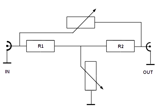
Attenuators matched to 50 Ohms will have a T- or PI-type configuration. The configuration we use is a bridged-T attenuator, which seems to be the only type suitable for continuous operation. Because we want a decibel scale, a logarithmic potentiometer should be able to do the job.
bridged-T continuously variable attenuator
R1 and R2 have a 50 Ohm value. The
potentiometer is a 2-gang logarithmic type which is
connected in such a way that while one section increases in
value, the other section decreases. The maximum attenuation
you get depends on the potentiometer value, being about 30
dB for 1 kilo-Ohm. This was also the smallest value I could
get from the shop.
So what can we expect? These type of potentiometers are intended for low frequency use, how will they behave at higher frequencies? But there is something else: are they really logarithmic?
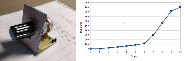
setup and measurement of logarithmic potentiometer values
As you can see from the graph: relationship between scale
(0-10) and resistance value is not truly logarithmic. To
reduce costs, these type of potentiometers are built with 2
different values of resistance with linear behavior, which
produce a logarithmic approximation. In fact, we have 2
straight and combined lines in one graph. Next, what kind of
losses can we expect?
So what can we expect? These type of potentiometers are intended for low frequency use, how will they behave at higher frequencies? But there is something else: are they really logarithmic?
setup and measurement of logarithmic potentiometer values
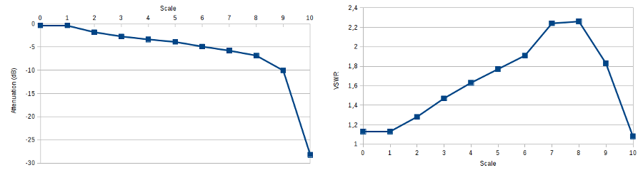
attenuation (left) and VSWR (right)
versus scale
Measurements were done at a frequency of
10 MHz. As you can see from the left graph, there is a
nice relationship between attenuation and scale up to
90%, after that the value increases rapidly. Insertion
loss measured is -0.36 dB, which is about 8%. The right
graph shows a maximum VSWR above 2.2, another loss in
power of 13%.
In conclusion, this type of attenuator is not intended for accurate setups, but it might still be useful at driver level or at the input of a receiver where loss is not critical and we have plenty of signal. Losses are caused by the potentiometer design: they are not suited for high frequencies and not exactly logarithmic. Thats why good variable attenuators are so expensive: they are difficult to make!
I have used an ancient Hewlett Packard (now Keysight) 8753A network analyzer to do my measurements.