Welcome to
PE1RAH’s
MODE-UV lineair transponder design for P3e.
Before I left on a world-travel in October 2003 I made
an SMD MODE-UV transponder for P3e.
A prototype of this transponder has also been tested
on a high altitude balloon in Germany, with good results. Unfortunatly, during
my travel I got the information that this transponder was not good enough to
fly on the P3e satellite.
As a designer it doesn’t mean for me that everything
ends with this. During my 10 month travel I think out a way to make a better
design, but it has to be in a short time, and with less technical risk.
When I finally arrived home again from my long travel
in August 2004 I directly started working on my new idea. The idea was to make
the transponder in good old (none-SMD) component style, and cut the whole
system in separate modules. The small separate modules make it much easier to
measure and when problems occur only a small module has to be changed instead
of a whole design.
After my travel, in just 6 weeks, I made a prototype
design ready and present it in Bochum (Germany) at the 30th
aniversary of AMSAT-DL. On the following link of AMSAT-DL my experimental
prototype can be seen:
This experimental design I finally improved into a
flight version transponder, and now, about 3 months later I can show some more
interresting pictures. The transponder is still not ready, and there has to be
done a lot of work to finish it completely. The work is not only soldering, but
also lot of testing to be sure that the transponder will work under all
conditions. Unfortunatly my free time is very little (just few hours a day) but
when I can contribute to have more linear transponders in space I am not
complaining J
To all AMSATs around the world… Instead of only
talking I just show you what I have for you J
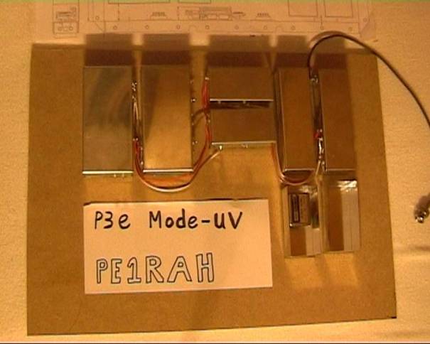
Left on the paper you can see the drawings of the
module placements. On the right you can see the modules I already made.

Another view…
Ofcourse there is something inside J
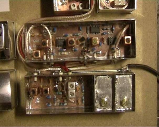
What is what?
The most right-top (long-small box) is 435MHz to 1st
IF converter. The one on the left to it (also long-small) is the 1st
IF to 2nd IF converter with AGC control.
In the middle, on the top is the UHF-receiver local
crystal oscillator. In the middle-below is the VHF transmitter crystal
oscillator.
The second from left box is the IF combiner unit. Here
all separate IF’s from RUDAK, Telemetry, 10m RX and 70cm RX are combined to one
IF with extra care of intermodulation.
The most left box is a transmitter upconverter, from 1st
IF to the 2nd IF. This module has a phase and envelope output, to
drive a high efficient HELAPs amplifier.
·
What is failing is the converter from 2nd
IF to 145MHz, an IF RX splitter, and the crystal filter matchings.
·
All three things are under construction, but
are not concidered to be problematic.
Some more close-ups:
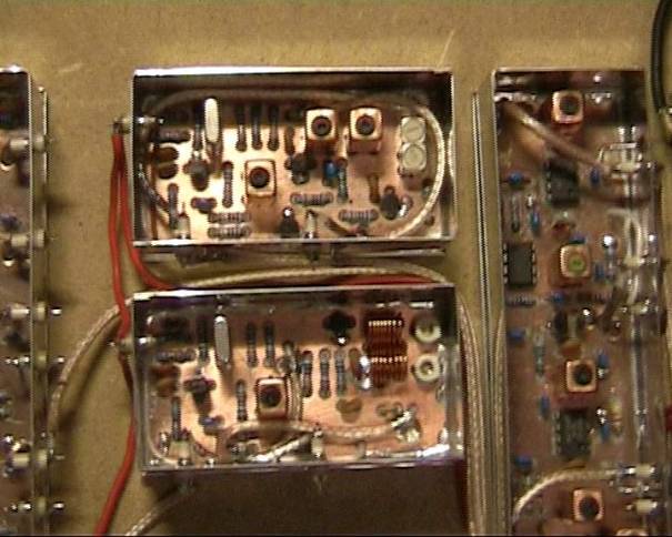
Below: 70cm RX to 1st IF;
Top: 1st IF to 2nd IF, AGC
control

Below: The VHF transmitter crystal oscillator
Top: The UHF receiver crystal oscillator

Right: 4x IF combiner (2 inputs are on/off
switcheable)
Left: 1st IF to 2nd TX IF
up-converter, with phase and envelope output to drive HELAPs high-efficient
final amplifier.
73 de PE1RAH,
William Leijenaar…
This page is designed
and created by PE1RAH. (William Leijenaar).