M15A tape recorder Wireless Remote Control


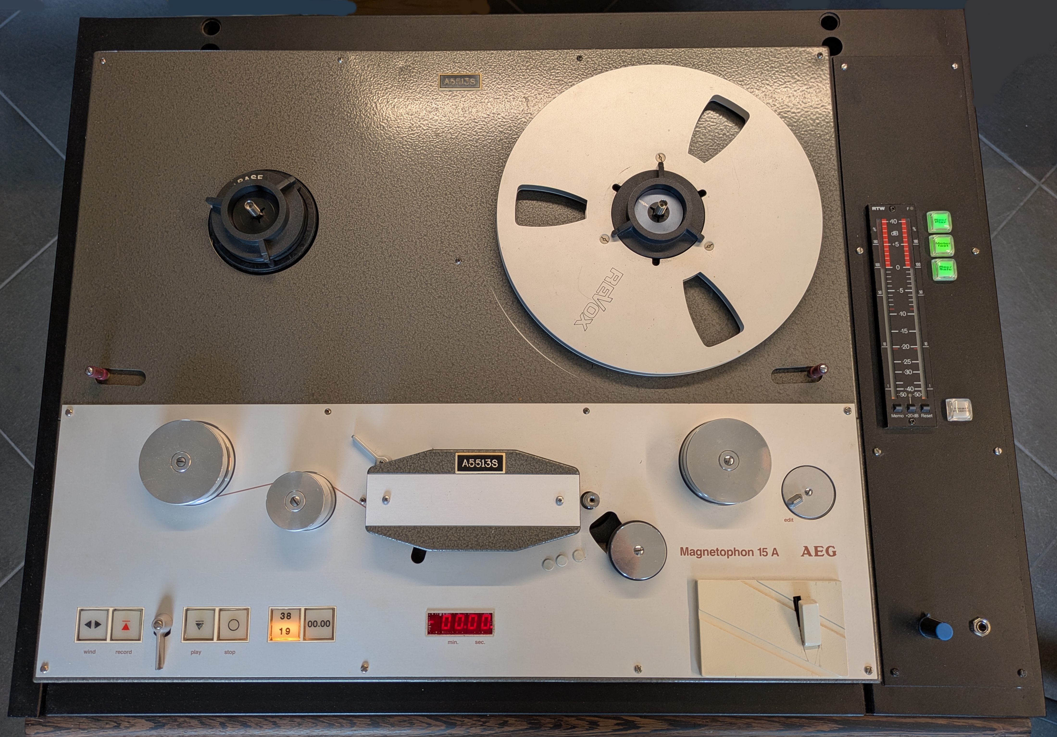
The M15A studio tape recorder (designed around 1975) can be remote controlled with a special remote control adapter card(BC-FA-1), to be placed in the recorder motor control card cage.
Via a 37 way connector this card is connected to the actual controlpanel (FS15A), somewhere else in the studio-room. The thick multi-wire cable between recorder and panel is pretty inconvenient, reason to look for a wireless solution. One of the non negotial requirements was that no modification of the recorder electronics should be needed.
The communication between recorder and panel is bi-directional, commands are given with (illuminated)pushbuttons on the panel and the recorder responds on a succesfull command with switching on a lightbulb in the button. In this way the operator knows for sure that the given command is successfull, even when the recorder is not in sight. So the wireless data connection should be full-duplex. After some research I found the (cheap) Bluetooth HC-05 modules. These small bluetooth modules can be configured to connect to each other automatically on power-up and etablisch a two-way RS232 like communication path. The outgoing and incoming RS232 messages have to be translated into simple contact closures to control the recorder and light the buttons on the controlpanel. This is done with two Arduino Nano cpu modules, also cheap, available and easy to program.Important remark: Before the HC-05 modules can be used in this application they need to be "paired" and properly configured. See the end of this page.
How does the original wired remote control work? The recorder has a fairly complicated control system, build with CMOS logic and located on a number of cards in a card cage below the recorder deck. The machine can be equipped with a number of options like timecode control and remote control. For all these options a additional card needs to be plugged in, the card provides the interface to the internal control logic. Remote controlling needs the BC-FA1 card in conjunction with the FS15A controlpanel.
The BC-FA1 and FS15A: See schematic diagram fig 1. On the left we have the control inputs, HALTB, WIEDB AUFNB etc etc. all with pull-up resistors. A command is given by pulling one of these lines low, this is done by one of the pushbuttons on the external control panel FS15A. ( see schematic diagram fig 2.)
The command is processed and when accepted one of the darlington transistors on the right side of fig 1 is put into conducting state. This pulls one of the lines HALTM, WIEDM etc etc. to ground and the respective button in the controlpanel is illuminated. This is a very robust way of controlling however more than 20 wires are needed between the BC-FA1 and FS15A.
Fig 1 BC-FA1 schematic diagram

Fig 2 FS15A schematic diagram

The wireless solution
My project uses two HC-05 bluetooth modules, one in "master mode" and the other in "slave mode". The output of such a module is TTL-level RS232 communication. The idea is to create a "status word" in both interfaces that reflect the state of the input and output lines of the BC-FA1 and the state of the pushbuttons on the panel. This status word is updated every time the status changes and immediately send to "the other side". This is the task of the Arduino Nano.For the illuminated pushbuttons I have choosen the NKK KP01-15 series buttons, they are rather expensive but very nice (and available at Digi-Key at the time of writing this....). They have three color LEDS (red,green and blue). Not needed,but buttons with single color Leds where not available. Also two C&K switches are fitted for the speed setting and mono/stereo switch. The selected speed is shown with a yellow LED beside the switch.
Finally we have a green LED signalling that the capstan speed is "in lock" (bereit). Five buttons control the tape drive mechanism, the sixth button is the "parallel" button. In the original FS15A panel this is a locking button. I could not find such, so the locking behaviour is realized in software. One push is "On" and stays on until a second push (toggle function). On top of this, the state of the parallel button is saved in EEprom, so after power down and up again the last known state is restored.
The "parallel on" state makes it possible to control the recorder both on the remote panel as locally on the recorder itself. When the remote switch is pressed on the recorder and the bluetooth connection is not established or lost, the slave interface puts the recorder automatically in the parallel mode, thus preventing entering an uncontrollable state.
The Master control module
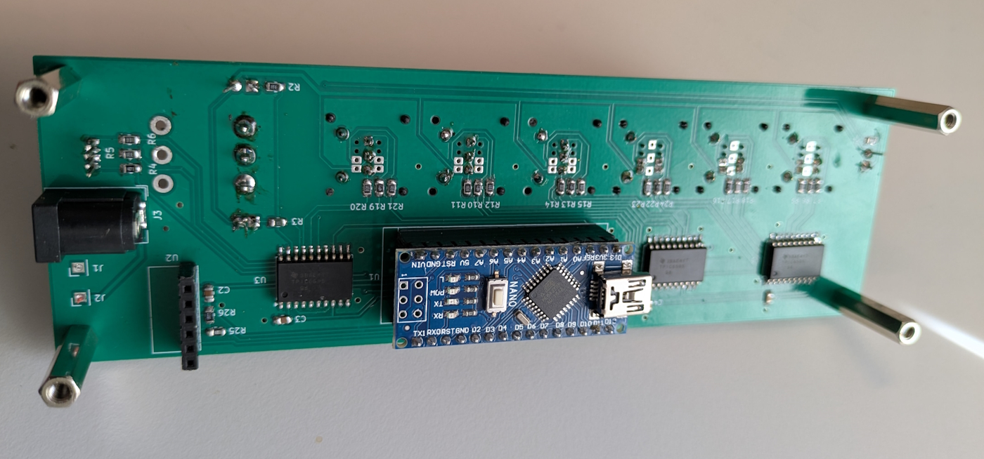
Although not needed, all the leds in the buttons are connected, together with the remaining leds there are 24 LEDS to drive. The Arduino Nano does not have that much output lines, so the construction with three 8-bits shift registers is used. This registers are compatible with the well known 74HC595 shift registers, but have open drain outputs, capable of sinking 200mA per channel. So almost any led or lightbulb can be driven with this chip. The switches and buttons are directly connected to the Nano. The HC-05 module has an 3.3Volt interface so a voltage divider with R25 and R26 is used to reduce the Tx output voltage from the Nano. The Nano connects to the HC-05 with software serial communication, leaving the hardware serial port for programming and debugging. The separate RGB LED shows the state of the module: Green for Power on but no connection. Blue for connection established. Red for error(not implemented yet) The master module should be fitted in a plastic housing to prevent blocking of the wireless signal. Under normal conditions the range between master and slave should be at least 10 meter.
Fig 3 Remote Control master schematic diagram

Fig 4 Remote control master pcb version 1.0 DC powered 5 volt


The Slave control module
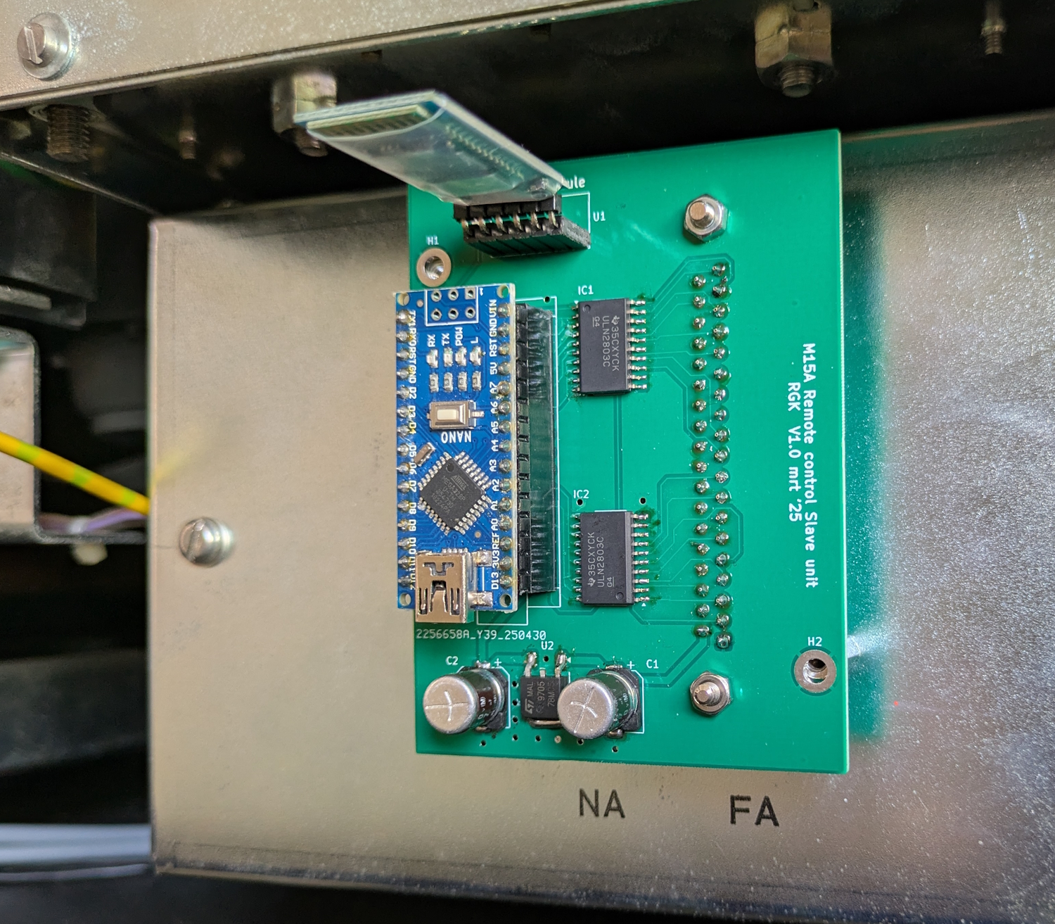
To the left we see the 37-way connector to the recorder. The ULN2803's provide a safe interface to the 12 volt in/output lines of the BC-FA1 card. The HC-05 module is connected the same way as in the master module. A linear voltage regulator (U2) reduces the 24V power from the recorder to 5V for the Arduino and HC-05. Finally a blue LED shows the connection state. The pcb is constructed so that it can be placed direct on the BC-FA1 connector after removing the small metal cover plate. Special attention is needed for the position of the HC-05 module. The RF signal path may not be obstructed with metal screening. It would make the wireless connection impossible or instable.
Fig 5 Remote Control slave schematic diagram

Fig 6 Remote control slave pcb version 1.0 to place inside M15A recorder


Configuring and pairing the two HC-05 modules.
Bluetooth connections are normally point to point, one transceiver is the master the other is slave. The master needs to know which slave it should connect to. On power up it starts looking for a slave that matches the address stored in its connection table. If this slave is detected, they connect automatically. A good description of the modules and their configuration is found at: Bluetooth pairing tutorial
In short: Put the first module in the AT mode, check if is is in the "slave" mode, set the baudrate to 38400 and ask its mac address. Copy this address with ctrl-c or write it down somewhere. Now connect the other module, and put it in AT mode. Check and set it in the master mode, set the baudrate to 38400 and put the slave address, found in the previous step, in the connection table. After this, when you apply power to both modules (+5v) they connect to each other after about 30 seconds. This is shown by two short led blinks every 2 seconds. Now they are ready to use, it does not matter which unit gets the master module or the slave module.
Rob Krijgsman June 2025