
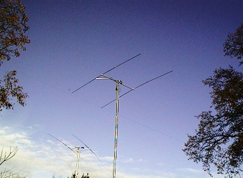
(15 M and 10M 2-element beams in the authors garden - Photo by D.A.Reid)
By David Reid - PA3HBB / G0BZF
Leenderweg 46
5591 JE Heeze
Netherlands
Date Started: 24 Jan 1999.
The Advantages of a Delta Match
The Components of a Delta Match Beam
Ø
The Design FrequencyØ
The Driven ElementØ
The Director ElementØ
The Boom LengthØ
The Delta ArmsØ
The Delta Arm ThicknessØ
The Delta Arm SpacingØ
The 4:1 Matching BalunØ
A 20M Beam ExampleØ
A 15M Beam ExampleØ
A 10M Beam ExampleØ
The Design ExampleØ
The Driven ElementØ
The Director ElementØ
The BoomØ
The Delta ArmsØ
The Delta Arm SpacingØ
The 4:1 Matching BalunIn most of the book on antennas there is a section covering making VHF or UHF beams using a Delta match to feed the driven element. In this article, I explore the use of such an easy matching system on H.F. antennas. Thought by some to be impractical to use such large matching networks, I hope to disprove these doubters and show that it is not only practical, but also very effective and easy. This article will cover some technical and some practical approaches to building and designing Delta matching networks. Wherever possible, I have included some practical information to help with the design of an effective antenna. The formulae in this article are for creating two-element beams with an architecture of a Driven Element and a single Director. This creates an antenna with the most effective gain whilst keeping the boom length as short as possible.
I've been designing beams and other antennas since before I was licensed in 1981, however, I don't confess to knowing it all, nor of having a great background in RF techniques, but I have designed quite a few good antennas (and a number of worthless ones as well). The formulae and techniques discussed in this article are based on real experience and practical methods which I have been using for many years. The designs, resulting from these formulae have been tested in a computer simulation and also built and tested. I have deliberately simplified the equations used in this article, in order to produce results which others can also produce using nothing more that a paper and pen (or perhaps a pocket calculator).
The Advantages of a Delta Match
There are a number of advantages to a Delta match feed system and these outweigh any disadvantages (most of which can be overcome). Of course, as published in many other books and articles, the advantages of a Delta match at VHF and above are quite clearly stated, so I will not repeat these here. However, turning to H.F., then these need to be spelled out, as I have never seen them written down before.
The first major advantage is that of mechanical stability of the antenna -there is no need to split the driven element and the centre point can be grounded to the boom for static protection as well as lightning protection. Especially at the lower H.F. frequencies, like 20 metres, these are great advantages to the home constructor.
The second major advantage is that of bandwidth. Because of its inherent design as a low-loss 4:1 balun (using coaxial cable as the impedance matching section) it is quite low Q and therefore provides a much better operating bandwidth than some higher Q matching networks such as the Gamma match. If the materials are chosen well, there is no reason that whole portion of any amateur band can be covered without needing to re-tune the antenna, though there will a slight loss of gain and front-to-back ratio, as would be expected with any antenna. There are some simple formulae that allow the whole antenna to be calculated, with repeatable results, regardless of the frequency in use.
At H.F. (3 to 30 MHz), the formulae provide numbers which create a beam that works, and works well, with a low VSWR and an appreciable gain. More about these formulae later in this article.
I decided to try my first Delta matched antenna about two years ago, I built a 10-metre 2-element Yagi in the conventional manner (one driven element and one reflector). The boom of the antenna was almost two metres long, and the performance was quite good with a forward gain of about 5 dBd (gain over a 1/2-wave dipole at the same height, in the same location). The front-to-back (f/b) ratio is about 12dBd and that is about 2 S-points.
I discovered that the 10-metre beam boom could be shortened, without sacrificing any gain or front-to-back ratio by using a director instead of a reflector. The optimum boom length worked out to be approximately 0.09 wavelength. With this configuration, it could be scaled to any frequency very easily and after building/designing the same configuration of Delta match, the resulting lengths of the individual components could be defined in a set of simple equations. To prove the equations and formulae, I reversed the process and designed a 15-metre yagi, for 21.050, I typed the numbers into a spreadsheet and cut the components to the resulting lengths. This was then assembled and put up on my 10-metre pump-up mast for testing. It was perfect - SWR 1.1:1 at the design frequency of 21.050!
Next, I decided to try another test and redesigned the antenna to a centre frequency of 21.350, although the SWR was only 1.6:1 with the original design. Again, the formulae proved correct and after adjusting the delta match network to the new parameters I had a 1.0:1 VSWR on the new frequency. There was not a lot of difference in the matching dimensions, but it did prove that my formulae were correct and reproducible.
Now, the real test, I made a 2-element beam for 20 Metres, based on the formula, and low and behold, this was also a near perfect 1.1:1 VSWR at 14.050 (the designed frequency). Now that I had proved the formulae, I thought I would write it up and present it to the world through this article.
First of all, I have designed all these formula to work in the metric system in centimetres. If required, multiplying the resulting numbers by 2.54 makes the conversion to 'decimal inches'. To make the 'decimal inches' number into a more useful calculation in feet and inches, take the intermediate number and divide it by 12 to get the calculation in a decimal version of feet. Use the table below to convert the part on the right of the decimal point to get the round number of inches. (When working with H.F. antennas, the calculations will be accurate enough). The part on the left of the decimal point is the full number of feet (see
Example 1).
|
Table 1: 'Decimal Inches' conversion |
|||
|
Decimal number |
Round Inch |
Decimal number |
Round Inch |
|
.9166 |
11" |
.4166 |
5" |
|
.8333 |
10" |
.3333 |
4" |
|
.7500 |
9" |
.2500 |
3" |
|
.6666 |
8" |
.1666 |
2" |
|
.5833 |
7" |
.0833 |
1" |
|
.5000 |
6" |
<.0300 |
0" |
Example 1
Calculation (c)= 535.7 cm
Divide by 2.54 to get 210.905 inches
Divide this by 12 to get 17.575 feet
So the whole feet equals 17 and the decimal part (.575) is looked up in the table. Looking at the table the closest value is 7" and therefore the length is 17' 7".
This calculation can be simplified to:
Calculation (c)/30.48
Which in the above calculation 535.7/30.48 = 17.575.
The 30.48 'magic-number' is obtained by multiplying the 2.54 by 12.
The Components of a Delta Match Beam
There are a number of components to the Delta match, so each will be handled separately, first with an explanation, then with the formula for a two-element beam and finally with an example.
The Design FrequencyThis is arbitrary - it does not matter what frequency you choose, but an obvious choice would be within the amateur bands centred on the portion of the band you prefer to operate on. For instance, if you only operate on CW then design the beam to be centred on the centre of the CW allocation. However, it is important that all the components are designed to work at the same centre frequency. This will be referred to as the Design Frequency (Dfreq).
Example Dfreq = 21.050
The Driven ElementThe Driven Element (Edri) of the beam should be resonant at the design frequency. This is done based on the standard formula:
Edri = (300 / Dfreq / 2) * K or (150 / Dfreq) *K
Where Dfreq is the Design Frequency in megahertz (MHz), 300 is the speed of light divided by 1000 and the whole is divided by 2, because we need only a half-wave for the Driven Element of the beam. The K factor based on tapered elements, and fixing of the driven element through the boom, is 0.9957. This formula can be further simplified to:
Edri = 149.35 / Dfreq
The reason the 'normal' K factor of 0.95 is not suitable is because it is used for linear elements and takes no account of the mounting method employed. Using a tapered element increases the K factor by a small amount - from 0.01% to 0.06%, and mounting the elements through the boom also increases the K factor from the 'normal' value seen in many books. I have calculated the K factor used for designing these type of beam by experimentation and reverse calculation based on this experimentation.
The diameter of the material used to make the beam has a small effect on the exact frequency of resonance, as does the shape and material of the element. If, for instance, the elements are tapered, then this will affect the exact length. In practice, though, this difference is so small that it can be incorporated into the simplified equation as a constant. Unless the diameter of the element is a substantial portion of a wavelength at the design frequency, this formula is suitable. This is usually known as the 'K' factor, and this figure becomes more critical as you go up in frequency, but at up to 30 MHz you can just use this single value, the Delta match network will handle any small deviation.
Example Edri = 149.35 / 21.050 = 7.095 metres for the Driven Element length
The Director ElementThe Director Element (Edir) is placed in front of the Driven Element (Edri) and is based on a percentage of the driven element length. The optimum length for this short boom beam is calculated using my simplified formula:
Edir = Edri X 92.37
Example Edir = 7.095 X 92.37 = 655.3 cm for the Director Element length
The Boom LengthThis depends on the architecture of the beam. If you use a driven element and a reflector, then the boom needs to be longer than if you use a driven element and a director. These formulae are based on the practical approach of getting the shortest boom length possible without sacrificing too much in gain and keeping the amount of metal in the sky to a minimum. This means the second option is best - a driven element and ac director in front of it. My formula is based on a boom length of approximately 0.12 wavelengths. This does imply that the front-to-back ratio is lower that would be ideal, however, as in everything, compromises are necessary. The front-to-back ratio is approximately 12dBd. This also allows the beam to operate over a wider bandwidth range. If the f/b ratio was made optimum, then the gain would suffer, or the bandwidth. I think full band coverage is more important than the f/b ratio, and the advantages of the shorter boom far outweigh the slight loss in signal rejection from the back of the beam.
It is surprising just how close the elements can be... as close as 1.7 metres on a 20-metre beam! So, the boom length (Blen) can be calculated using the following formula:
Blen = Edri / 0.06375 for the best compromise possible
Example Blen = 7.095 / 0.06375 = 111 cm boom length
The Delta ArmsThe Delta Arms (Darm) are calculated as a percentage of the Driven Element (Edri) length. This calculation has been reduced to its simplest form and is valid for all frequencies between 3 and 30 MHz. Each arm is cut slightly longer than required to allow connection to the element and the coaxial feeder and balun, but the distance between the connection points should adhere to the following calculation:
Darm = Edri X 13.51351 = Delta Arm length
Example Darm = 7.095 X 13.51351 = 95.88 cm for each Delta Arm
The Delta Arm ThicknessThe diameter, or thickness, of the Delta Arms is not too important, as long as it is smaller than the diameter of the driven element. I use 12.5-mm X 2-mm aluminium strip for the Delta Arms of all my beams, and this works very well. The thickness of the Delta Arms does, however, have an effect on the bandwidth, larger surface area arms producing a greater operating bandwidth. Using the largest possible diameter (or thickness) of Delta Arm, is therefore advisable. Another benefit of a thicker Delta Arm is one of support for the Driven Element, holding it more rigidly in place on the boom and this means that a lighter metal can be used for the elements, reducing the weight and the cost.
The Delta Arm SpacingThis is the critical calculation for obtaining a good VSWR. Again, I have simplified this calculation to one which is valid for all bands from 3 to 30 MHz. Adjusting the spacing between the two Delta Arms adjusts the impedance that the coaxial cable 'sees'. In general, the exact setting is not too critical on 20 metres, but on 10 metres, perhaps more adjustment will be required. The Delta Arm spacing (
Asp) calculation is as follows:Asp = Edri X 19.8198
Example Asp = 7.095 X 19.8198 = 140.62 cm for the Delta Arm Spacing
It is important that the Delta Arms are symmetrically spaced from the centre of the element.
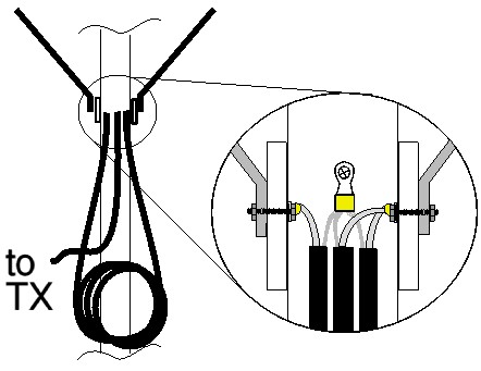
The 4:1 Matching BalunThe 4:1 matching balun (Mbal) is made from a half-wave of 50-ohm coaxial cable. Therefore, it can be based on the length of the Driven Element (Edri) and calculated by multiplying this by the modified velocity factor of the cable (this is higher than the specified 66 value to compensate for the shorter length of Edri). This simplified formula, for calculating the length of RG58U 50-Ohm coaxial cable required, has been thoroughly tested and proven to work for all frequencies from 3 to 30 MHz. To make a 200-ohm match to the Delta Arms requires a half-wave of coaxial cable. The formula will have to be altered for coaxial cable of a different impedance or velocity factor. However, RG58U is widely available and it is suitable for all H.F. power limits up to the UK legal limit (400Watts). The formula is:
Mbal = Edri X 71.17117
Example Mbal = 7.095 X 71.17117 = 504.9 cm of RG58U
If the matching section is not resonant at the same frequency as the driven element, high voltages can arise on the cable and cause flashover of the coaxial cable insulation, especially at high power levels. The physical layout of the balun should be symmetrical, but the actual shape and placement is not too critical. On 10M and 15M, coiling the coaxial cable into a ring of about 20 centimetres and taping this assembly to the boom is an easy solution. On 20M the length of the cable makes this a bit impractical and leaving the balun as a straight section running parallel to the boom works just as well.
These formulae are only valid for the close-spaced 2-element beams described in this article.
A 20M Beam ExampleLet us say we want a beam for the CW end of 20 metres but we occasionally venture up to the SSB section and we want the beam to work there as well. Therefore, our design frequency is going to be 14.100 (the bottom of the SSB section). Though the beam will work over the whole band, the front-to-back ratio and the gain deteriorate the further we QSY from the design frequency.
|
Parameter |
Formula |
Design Value |
|
Dfreq |
------------ |
14.100 MHz |
|
Edri |
149.35 / Dfreq |
10.592 metres |
|
Edir |
Edri X 92.37 |
978.38 cm (or 9.783 metres) |
|
Blen |
Edri / 0.06375 |
166.15 cm |
|
Darm |
Edri X 13.51351 |
143.14 cm |
|
Asp |
Edri X 19.8198 |
209.93 cm |
|
Mbal |
Edri X 71.17117 |
753.84 cm |
If we calculate the resonant frequency of the Director, we find that it is well out of the amateur band, being resonant at about 15.25 MHz. This is a good thing, because the directivity and gain, as well as the radiation pattern of the beam would deteriorate drastically, if we were to tune-up or operate on the resonant frequency of the Director Element.
A 15M Beam ExampleLet us create the 15-metre beam for the SSB end of the band. About 21.275 is the centre of the SSB section, so let us use that as our Design Frequency (Dfreq).
|
Parameter |
Formula |
Design Value |
|
Dfreq |
------------ |
21.275 MHz |
|
Edri |
149.35 / Dfreq |
7.020 metres |
|
Edir |
Edri X 92.37 |
648.44 cm (or 6.484 metres) |
|
Blen |
Edri / 0.06375 |
110.12 cm |
|
Darm |
Edri X 13.51351 |
94.86 cm |
|
Asp |
Edri X 19.8198 |
139.13 cm |
|
Mbal |
Edri X 71.17117 |
499.62 cm |
In addition, the resonant frequency of the Director is about 23.05 MHz, which is, again, well outside the amateur band.
A 10M Beam ExampleFor 10 metres, lets choose a centre frequency of 28.500 (the centre of SSB activity).
|
Parameter |
Formula |
Design Value |
|
Dfreq |
------------ |
28.500 MHz |
|
Edri |
149.35 / Dfreq |
5.240 metres |
|
Edir |
Edri X 92.37 |
484.02 cm (or 4.840 metres) |
|
Blen |
Edri / 0.06375 |
82.20 cm |
|
Darm |
Edri X 13.51351 |
70.81 cm |
|
Asp |
Edri X 19.8198 |
103.86 cm |
|
Mbal |
Edri X 71.17117 |
372.94 cm |
The resonant frequency of the Director is about 30.8 MHz, which, again, is well outside the amateur band.
Ok, so we now have the formulae and a few examples of beams and now it is time to put the theories into practice with a practical design. This section of the article is based on experience I gained over the years of designing many different antennas and, in particular, with the work I have been doing on the development of these formulae.
The Design Example
The example I want to describe here is for a 15 metre, 2 element beam. If we look back to the design example, stated earlier, we can use the data to design a beam for 21.275 MHz.
|
Parameter |
Design Value |
|
Dfreq |
21.275 MHz |
|
Edri |
7.020 metres |
|
Edir |
648.44 cm (or 6.484 metres) |
|
Blen |
110.12 cm |
|
Darm |
94.86 cm |
|
Asp |
139.13 cm |
|
Mbal |
499.62 cm |
The Driven Element, as can be seen from the table, should be 7.02 metres long. This assumes that the element is tapered and not a substantial portion of the wavelength at the design frequency. I chose a maximum diameter of 1.6 centimetres and a minimum diameter of 10mm, which is well within these limits. The reason for choosing this diameter of tubing and the overlapping element sections is three-fold, first, it keeps the weight of the very long element to a minimum, second, the 1.3 centimetre tubing does not fit well into the 1.6 cm tubing and third, all the components were easily available at my local DIY shop.
C B A B C

|
Element Section |
Length (cm) |
Diameter (cm) |
|
A |
200 |
1.6 |
|
B |
200 |
1.3 |
|
C |
200 |
1.0 |
|
L |
702 (7.02 m) |
--- |
The Director Element was made in a similar manner to the Driven Element, but to a total length of 6.484 metres. Section A of the Director is 2 metres long and section B is also 2 metres long, which overlaps section A by approximately 750 mm at each end. The two section C tubes are 2 metre lengths of 1.0 cm tubing that is slipped into the 1.3 cm section B tubes, one at each end and secured so that the overall length is correct.
C B A B C
|
Element Section |
Length (cm) |
Diameter (cm) |
|
A |
200 |
1.6 |
|
B |
200 |
1.3 |
|
C |
200 |
1.0 |
|
L |
648.44 (6.484 m) |
--- |
The Boom
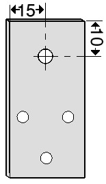
The boom was made from a section of aluminium stock with a 25 mm square thick wall bar. It was originally designed for making modern DIY furniture and is relatively cheap, but durable and not brittle. A 2-metre length was purchased and cut down to 1.2 metres. 4.5 cm from each end, a hole was drilled to fit my 16-mm hole-punch (purchased from Maplin Electronics).
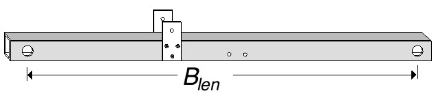
I found that the hole-punch is the best way to get clean, tight and true holes, it is well worth the investment. With the holes in the boom cut and the edges filed clean, the work on the boom is complete, except for the mounting bracket. That will be the last thing to do, as we do not yet know the centre balance point of the completed beam, and it is better to have the boom to mast clamp positioned at the gravitational centre of the boom.
The Delta Arms
The Delta Arms were made from one 2 metre strip of aluminium (12.5mm X 2mm). Two pieces were cut to 97 cm each. When bent to the correct shape, this creates the 94.86-cm length given in the table.
[See Delta arm drawing]
Two plastic insulators were cut from a sheet, to a size of 5 cm by 3 cm with a thickness of 0.15 cm. These form the connection point for the coaxial cable, the two Delta Arms, and the 4:1 matching balun. A 3.5-mm hole is drilled in each plastic insulator, in the position shown in the diagram below.
According to the table, the spacing between the two Delta Arms should be 139.18 cm. The first section of tubing of Driven Element (A), was inserted through the boom and centred. Then measurements were taken to each side of the centre line for the positioning of the Delta Arm to Driven Element connection point. During the test phases of my designs, I used hose-clamps (jubilee clips) to hold the Delta Arms in the correct location, Once the formulae were created and tested, now I simply drill a hole and pop-rivet the Delta Arms to the Driven Element at the points measured. So far, this has worked perfectly. In the Design Example this positions each Delta Arm exactly at 69.59 cm symmetrically around the centre point.
The 4:1 Matching BalunThe next, and final piece of the beam is the 4:1 Matching balun. Looking at the table we need a piece of 50-Ohm RG-58U with a length of 499.62 centimetres. I cut a 5-metre (500-cm) length which is close enough, allowing for the connections. See the drawing for details of the electrical connections required. I used a crimp tool to put large crimp-on ring connectors on the ends, where the coaxial cables join. This makes assembly and disassembly possible, while ensuring good connections. All the connections were also soldered for extra peace of mind. The common ground connection is screwed via a zinc-plated sheet metal screw into the boom and the two free ends are bolted through the plastic insulator and the Delta Arm. A small box was built, from pieces of the insulation material and placed over the connecting points to keep the weather out.
The first sections of the Driven and Director elements (A) are inserted through the holes in the Boom and positioned so they are centred, before being screwed in place with a single screw from the bottom upwards. Use a zinc-plated sheet metal screw, one for each element section.
The Delta Arms can now be riveted to the Driven Element, after careful measurement.
The free ends (closest to the boom) should be bolted temporarily to the plastic insulator plates and the plates are located, one on each side of the boom. These are then screwed in place using 3 zinc-plated sheet metal screws.
The Balun and coaxial cable assembly, made earlier, can now be secured to the boom. The connections of the balun/coax assembly to the Delta Arms, through the plastic insulator, can now be made.
Sections (B) of the Driven and Director elements are connected to section (A) using 3 zinc-plated bolts in each leg. The overlap with sections (A) are first measured and the elements taped in place before drilling and bolting the elements in place. Attaching the elements in this manner means that we can dismantle the beam for easier storage, by simply un-bolting the long elements and storing the Boom/Delta Match sections separately.
Sections (C) of the elements is inserted into the section (B) and measured to length. Do not, at this stage, fix these in place permanently, instead, use some electrical tape to hold them in place, temporarily.
Find the centre balance point of the beam by picking it up, near the centre and moving your hand until the beam sits parallel to the ground, mark this position on the Boom. I use exhaust clamps to mount the Boom to the mast, but normal 'U' type antenna brackets will also work. Drill 2 holes through the Boom, symmetrically around the point you marked, at the correct spacing for your Boom-to-mast clamp.
Mount the beam, temporarily about 2 metres off the ground and check the SWR on an accurate VSWR meter. If you followed the dimensions carefully, then you should have a near 1:1 SWR at the design frequency - 21.275 in this case. Slight adjustments can be made to the resonant frequency by altering the length of the driven element. This is achieved by sliding the end sections (C). Slide them in, to move the resonant frequency up and out to move it down. Remember how much you moved it and move the Director by the 92% of same amount.
For example, if the resonant frequency is too low, slide each section (C) of the Driven Element in by 10mm. This means you adjusted the length by a total of 20 mm. Therefore you need to adjust the Director Element by a total of 18.4-mm (9.2-mm on each side).
Because the 4:1 Matching Balun is quite a low Q device (and therefore, a large bandwidth), it should not need adjusting.
However, if your VSWR is exceedingly high (>2:1) then you should make a new balun and fit this to the antenna. In all the HF antennas I have designed and built using a Delta Match, I only once had a horrible VSWR, and it turned out that I had measured the balun length incorrectly and it was one metre too short. Therefore, it is always best to check the dimensions of every component twice before assembling the beam.
When the beam is correctly resonant, you can rivet the section (C) ends to the section (B) ones, using 2 rivets per section. The ends of the elements should be filled with a sealer compound, or hot-melt glue to stop the elements whistling in the wind.
Place the beam on the mast at its full operating height and check the VSWR again
There you have it, a completed 2-element beam for 15 metres.
Photo of 20M delta matched yagi at the QTH of PA3HBB