
A portable three element 6M yagi
for less than twenty pounds!
by D.A.Reid PA3HBB / G0BZF
 Note:

   This article is copyright of the Radio Society of Great Britain as it was published

   in the November 1997 issue of the Society magazine - Radio Communication - please do not use

   this article without checking with the RSGB. This is the original text, I wrote, and differs

   slightly from the published version.
Having just got myself a new Alinco DX-70 at Friedrichshafen, I required a simple beam antenna for the coming summer. So I looked at the criteria I needed...
1) Boom length of not more that 2M,
2) Reasonable gain,
3) Low cost,
4) Ability to dismantle easily, for transportation,
5) Easy assembly with the minimum of tools,
6) Easy and quick tune-up,
7) Lightweight.
First I needed some materials - and a visit to the local D-I-Y shop proved a rich source of available materials - they have a wide range of 1M and 2M aluminium tubing and box section.I settled for 12.5mm round hollow tubing in 2M lengths, for the main elements, with the next smaller size (10mm) making a tight fit. This is also hollow, though I bought a 1M piece of solid, as well - to make the Gamma match section. The boom is a 2M length of U section aluminium 25.4mm square.
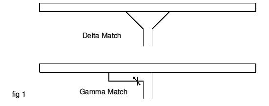
I had decided, due to my criteria, that a 3 element beam, in the traditional manner (1 reflector, 1 driven element, and 1 director) would suit my purposes well. Because of past experience on 2M with atmospheric noise (QRN) I also decided that the beam would be designed as a 'plumbers delight' - in other words, all the elements and the boom are at a common earth potential. This reduces some of the QRN, and static electricity which can be prevalent in other types of design. A design of this type limits the feeding arrangements to basically a Delta match (see fig 1) or a gamma match. I chose the Gamma match because of it's easy adjustment, bearing in mind I want an easy, quick tune-up and a transportable system.
So, having met all my criteria, it is time to set about building the antenna.
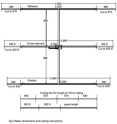
The first thing to do is to measure out the boom and drill the holes for the reflector and director elements.(see fig 2 and Table 1 for dimensions). The 12.5mm holes are marked and drilled with a smaller (6mm) drill bit, before the larger holes are drilled. This makes the job much easier. Care must be taken to get these holes straight and level in both directions, otherwise the antenna will look very odd indeed. Using a small round file, file a notch in the top side of each of the four holes, this notch should be just large enough to pass the head of the screw which holds the 10mm tubing to the 12.5mm tubing (see fig 3). The reason for doing this is simple, it makes it easier to dismantle or assemble the elements on the boom.
In the flat side of the Boom drill a 2mm hole on the centre line, this is for the screws which hold the elements in place while the antenna is being used (see fig 3).
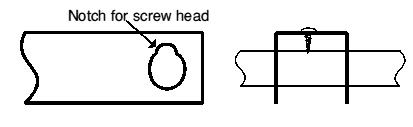
Fig 3 - Details of the element holes (reflector and director)
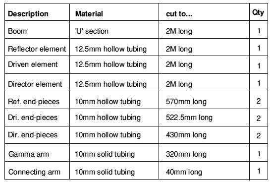
Table 1 Correct tubing lengths
It is almost unbelievable, but the 'standard' sizes of tubing available are perfect for a 6M beam. I bought two 2M length of 10mm hollow tubing and carefully cut them to the dimensions shown in Table 1. So, one length gave me the correct lengths for four end-pieces! (reflector and director).
With these end-pieces cut to the right lengths, they were simply inserted into the 2M lengths of 12.5mm tubing and, after marking the correct length of the whole element. 2mm holes were drilled for the sheet-metal screws to be driven through both the 10mm and 12.5mm tubing to hold them together. Each screw was driven through the tubing in a similar manner on opposite sides. This is done on the director as well as the reflector (see fig 4).
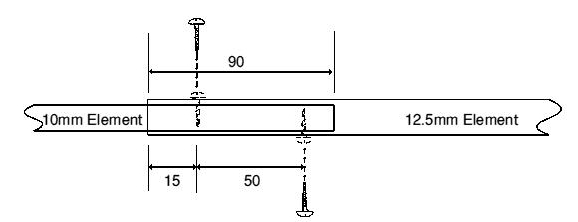
Fig 4 Detail of joining end-pieces to the main elements
The driven element is made of the same materials as the Reflector and Director, the method is the same, however, rather than being inserted through the boom, it is made separately and mounted through a plastic weatherproof box, which houses the 50pf capacitor and the Gamma arm assembly. Then the whole driven element and box assembly is mounted, with a screw through the box and into the boom and allowed to swivel parallel to the boom - for easy transportation. At this stage, the 10mm tubing and the 12.5mm tubing are not yet screwed together. This is so that the 12.5 mm tubing will fit tightly into the connections box.
The extra things which must be done to the Driven element are holes for the Gamma arm must be drilled in the 12.5mm tubing. These holes allow connection of the Gamma arm by a screw inside

Fig 5 The Gamma arm assembly
the tubing. A larger hole (8mm) is drilled through one wall of the tubing and a 2mm hole is drilled in the opposite wall. The reason for the 8mm hole is to allow a screwdriver access to tighten the element-to-Gamma-arm screw. After fitting and testing, the 8mm hole can be filled with putty or simply taped over with weatherproof tape.
To get the correct location of the Gamma arm holes, first find the exact centre of the Driven element and then measure out 305mm and this is the centre-line for the holes. At the centre of the element, another 2mm hole must be drilled, for the shield connection of the co-axial cable.
The connections box needs to be drilled to take the Driven element, Gamma matching arm and the capacitor shaft. The first holes to mark and drill are for the Driven element. These were carefully marked on each end of the bottom half of the plastic box, then drilled with a 6mm pilot drill and then again with the 12.5mm bit. The Gamma arm hole is drilled 40mm away from the element hole, and is only drilled in one end of the box. The Driven element and 1M aluminium rod are placed into the box and a suitable position for the capacitor located and marked for drilling. The capacitor I used came from the junk-box and the exact position is not critical, as long as it does not foul on the element or Gamma arm (see fig 6).
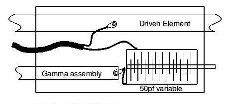
Fig 6 The connections box
A hole is required to screw the connections box to the boom, this is a 2mm hole drilled in the centre of the box. This screw goes through the plastic box and into the boom from the top side.
The other hole required at this time is one for the co-axial cable This is drilled in the same end as the Gamma assembly hole in the centre of the box.
With the solid 1M length of aluminium rod, measure and cut 320mm off. At one end, drill a 2mm hole for the connection point of the capacitor. 90 degrees out from this, at the other end of the rod, drill a 2mm hole straight through the rod. Using a 6mm drill bit, drill half way through the rod to make a countersunk hole in the rod (see fig 5). This is the attachment point for the Gamma connecting arm.
From the leftover length of aluminium rod cut a piece exactly 40mm long. With a file, one end must be filed to fit the Gamma arm, and the other end filed to fit the 12.5mm tubing. If a drill-press is available, it can be used to make a perfect job, by drilling through the rod with the correct size of drill bit. However, the file also works well, though it does take a bit longer.
In each end of the Gamma connecting arm a 2mm hole is required for the fixing screws (see fig 5).
Using a sheet-metal screw, screw the Gamma connecting arm to the Gamma arm forming an 'L' shaped gamma assembly. Place a screw through the 8mm hole in the Driven element and screw the Gamma assembly to the element using a sheet-metal screw (see fig 7).
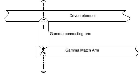
Fig 7 Connecting the Gamma arm assembly
Slide the connections box over the Driven element with the hole for the Gamma assembly facing the Gamma assembly. Insert the Gamma assembly into the hole in the box and adjust the box until it is in the centre of the element. Now screw the end-pieces into the Driven element in the same manner used for the Director and Reflector (see figs 4 and 5 ).Fit the capacitor to the box and connect one side of the variable capacitor to the Gamma assembly, using the 2mm hole (drilled earlier) and a solder tag held in place with a sheet-metal screw. Feed the co-axial cable into the box from the outside and strip the ends ready for connection. The shield of the co-axial cable is soldered to a solder tag and screwed to the Driven element using a sheet-metal screw. The inner of the co-axial cable is soldered directly to the other side of the variable capacitor. All the external connections to the box can now be weatherproofed using hot-melt glue, epoxy or similar product.
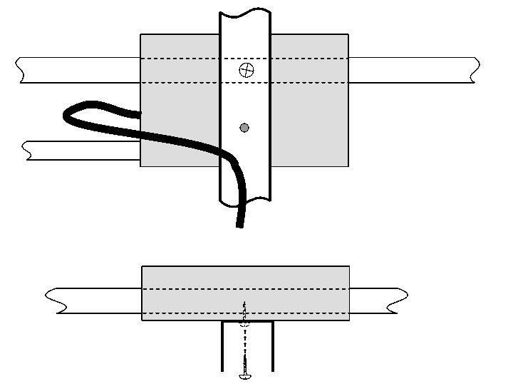
Fig 8 - Connecting the box to the boom
Locate the centre of the boom and drill a 2mm hole in the exact centre of the flat edge (see fig 8). The connections box is screwed to this point using a sheet-metal screw. Now, turn over the boom and align the Driven element so that the boom and the element are at 90 degrees to each other. Drill through the boom and the plastic box and into the Driven element with a 2mm drill bit.
This hole will be off centre and it holds the Driven element in the correct place when the beam is being used.
Fill the ends of all the elements with hot-melt glue, epoxy or a similar long lasting product to keep rain out of the tubing. After checking all the connections are good in the connections box, close the lid and seal against the weather. If required, drill holes in the side of the boom for, a mast-clamp.
The SWR should be quite good, if the dimensions in this article are followed closely.
Place the assembled antenna in a clear area at least 3M off the ground and check the SWR on a known SWR bridge. The SWR can be adjusted by turning the capacitor and checking again.
It is best to check the SWR at both band edged and set the SWR minimum at the centre of the band (see table 2 for SWR readings on the three beams I built for testing purposes).
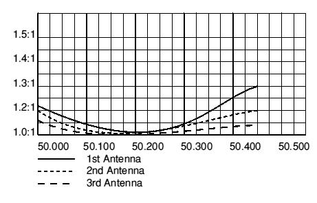
Table 2 SWR results for 3 experimental beams
Lay out all the metal pieces in a clear flat area. Rotate the Driven element to 90 degrees and insert the retaining screw through the boom and into the Driven element. Slide the Director through the boom and lock it in place using a screw through the boom and into the element. do the same thing with the Reflector. Mount the entire beam on the mast and raise it. Operate the radio and enjoy the DX.
To disassemble the beam, lower the mast, remove the antenna and the 3 screws in the boom.
Remove the Director and Reflector and rotate the Driven element through 90 degrees, only a single screwdriver is required for the beam and 3 screws.

Table 3 - Parts list
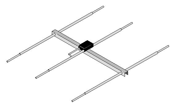
The complete three element 50MHz beam
The 3 element beam met all the criteria which I set out to achieve. It has proved robust enough for every day use at my home QTH as well as portable use on my 10 metre pump up mast. The total weight for the antenna is less than 3 kilograms!
I am extremely pleased with the DX I have worked with it. The total cost of the beam, excluding mast-to-boom clamp (and the pump up mast) was £18.63. To take the design further, I want to add another 2 elements to the front of the beam - making a 5 element beam on only a 4 metre boom. I think this can be done by reinforcing the 'U' boom with the next smaller size of 'U' shaped material and then adding a second 2 Metre section of 25.4 mm 'U' stock. The second thing I wish to try with this type of construction is to make a three-over-three stacked array using two of these antenna and the smaller 'U' sections to build the framework. Perhaps that will make another article later in the year.... Other projects, based on the same construction methods will be a 10 metre 2 element version, which should proved good fun.
I hope you enjoy the DX and constructing this antenna. I will look out for you all on the bands.
Best 73 es GUD DX.
de Dave
PA3HBB / G0BZF
Leenderweg 46
5591 JE Heeze
The Netherlands