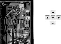
 Azimuth System
Azimuth Voltage
The azimuth voltages between the CU and the FodTrack interface were too low ( in my case ). That means : the rotator was turning further as wanted ..... Because of the warranty I did not want any modification to the CU or the rotator. In such a case a very good solution is : lower the 39 K resistor between pin 13 and pin 14 ( U2D ) or ( maybe ) better, replace the 10 K resistor between ground and pin 13. Place here a resistor with a higher value.
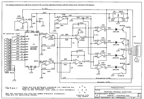
Click on the Schedule to Enlarge
Formula
1
|
Formula
2
|
 |
 |
| Original Version | Test Version, Modified |
Explanation
Because of the non inverted amplifier principle of this circuit ( U2D ) is :
U+ = U- ( U12 = U13 ) =>
|
=> |
|
Very simple mathematical manipulations delivered the formulas 1 and 2 above ( R13-14 and/or Rgr-13 ) hi. In this case I decided to change the value of the 10 K resistor ( Rgr-13 ) to ca. 14 K. The problem had been solved now.
An example ( calculation resistor ) English : click here.
Calculation resistor, Dutch : click here.
Azimuth Potentiometer
During a system test I measured the values of the potentiometer which had been mounted in the azimuth rotator.
If the rotator had been arrived at the left end stop, no zero ohm* was reached. Also, concerning the whole range, the tolerance was certainly not the same. And temperature influences were existing. The value of the whole range was much lower than 500 ohm. The azimuth potentiometer delivered only 455 ohm.
*Remark in most cases no electronic end stop is possible now.
A very simple and easy solution is : add a special voltage ( a 'zero adjust' voltage ) ! See Channel Master or click here.
Another solution : change the mechanical adjustment of the potentiometer, sometimes it is easy to do. Of course you have to take care when you mount the rotator parts again. Pay attention to the markers ! Otherwise it will be a disaster.
And a third solution : replace the potentiometer by another type. Preferably a 'metal' type. In most cases the pointing accuracy will be better now.
If the load ( the antennae ) is not very heavy, then the system works mechanically also very good.
Because of the better tolerance I also modified the interface a little bit. A good tolerance is useful ( even if a larger stepsize has been chosen ). The resulting tolerance will be better now.
Remark : the concerned rotator had a 435 degree range. Not 450 degree.
If you have the same type, use it as a 360 degree rotator.Elevation System
There were no problems with the elevation system, worked immediately for 100 % ( applied software was fodtrack 2.5 and 2.6 ).
Also the fodtrack interface is working very well, compliments to XQ2FOD !
Of course you can combine this interface with IT ( Instant Track ) and FODDRV ( and FLIPDRV and ORBITDRV ). Michael Radwick N8XKZ wrote FODDRV. Pay attention to the shift/offset function ! If this should be necessary ( fine tune position ). The Instant Track version I used was 1.50 A.F.
Click for download Instant Track1.50Apologies because of the bad translations. I did my best and hope that you could read it !
55 73 Leon [email protected]
http://members.home.nl/pc1l
http://www.qsl.net/pa3gje
http://www.qrz.com/pc1l
http://www.qrz.com/pa3gjeNB
Later on I got another 5500 azimuth rotator ( Yaesu Vertex ). But again these low potentiometer values.
The old one : 435 degree max and 455 ohm.
The new one : 447 degree max and 455 ohm.Manfred ( XQ2FOD, writer of FODTRACK ) calculated a few voltages delivered by the control box ( the CU, which has a 8 pin connector ). The end position voltages can be between 1.86 and 5.62 volts. Adjustable by VR3 and VR4.
Thanks to XQ2FOD ! Because of FODTRACK 2.6, the special BETA version and at least the very patient and clear answers on my questions, which I received from him. Fodtrack gives a lot of fun. Many amateur radio enthusiasts have already worked with fodtrack software and interface !
Click for download FodTrack 2.6
More about Manfred : http://www.qsl.net/xq2fod
Click for more recent programmes ( downloads AMSAT )Calculations
PS ( calculation of the resistor Rgr-13 and some explanation )
If this text is too complex or unwanted ( or annoying or boring, hi ) see below after point 3.
1 Go into the Fodtrack Calibration Mode. Now set AZ -> 64 => AZ = 90.7 degree ( on screen ! ). Value 1 ( end stop position north ) has been used in the fodtrack.cfg file ! Is it impossible to reach a real rotatorpoint of 90.7 degree via the adjust possibility ( CU ), please continue reading.
2 The actual voltage U14 ( ~ U2 ~ U3 ) will be 1.2 VOLT but ( in this case ) the rotator "turned too far" ( > 90.7 degree ). Because of the low rotator potentiometer value the voltage on pin 6 ( CU, 5500 series ) does not reach 1.2 VOLT at the 90.7 degree rotatorpoint. First, the real rotator pointing must become 90.7 degree. Then, you have to find the actual, resulting voltage. And at last, you must calculate the new resistor value. Please see below.
However, before positioning the rotator ( to 90.7 degree ) and to measure the voltage on pin 2 ( U2A ), we must do firstly something else. That is : set the wiper of the trimpotentiometer ( CU ) in the middle position, centrally. Because after replacing the resistor this potentiometer will be again in the middle position ( if the resistor calculation has been done well ! What is always nicely, convenient. Then, set the rotator pointing to AZ = 90.7 degree. Use for instance the manual function. Measure the new actual voltage at this 90.7 degree point. You will find it on pin 2 ( U2A ). This voltage will not be 1.2 VOLT, in this example it shall be lower. Here, it will be approximately 1 Volt.
3 We knew already : U12 ( ~ U13 ) is 0.25 VOLT ( AZ -> 64 ), see the values in the schedule. Now you will find Rgr-13 giving in ( see formula 2 ) : R13-14, U13 and U14 ( 39 K, 0.25 VOLT and 1 VOLT ). Result : 13 K. The system tolerance is not changing by replacing the resistor.
PS ( calculation of the resistor Rgr-13 without explanation )
If there are problems with the rotator direction, the pointing, ( because of 'incorrect' values of the rotator potentiometer ) :
1 Place the wiper ( sliding contact ) of the concerning trimpotentiometer ( CU ) centrally, in the middle position !
2 Bring the rotator exact ( as much as possible ) on 90.7 degrees azimuth, for example by means of hand control. Remark : this azimuth value concerns a code 1 endstop position ( calibration mode : azimuth value 64 ).
3 Now, to find U14, measure the voltage on pin 6 ( CU, 5500 series ) or pin 2 ( U2A ). U13 is 0.25 VOLT.
4 Give in these values ( mentioned above ) in formula 2 ( R in OHM or K, U in V ). You know now the desired, new value of the resistor.
PS ( about adjustments )
It is not possible to change or correct the described specific rotator position error by using a shift via the digital FODDRV offset. Use, for instance, a special voltage ( a 'zero adjust' voltage ) if possible.
PS ( berekening van de weerstand Rgr-13 )
Indien vanwege afwijkende potmeter waarden de rotor aanwijzing niet goed te krijgen is :
1 Plaats de loper van de betreffende instel potmeter ( CU ) in de middenstand !
2 Breng de rotor zo precies mogelijk op 90.7 graden azimuth, bijvoorbeeld door middel van handbesturing, denk eraan, deze azimuth waarde geldt voor een code 1 eindstop positie ( calibratie mode : azimuth waarde 64 ).
3 Meet nu om U14 te vinden de spanning op pin 6 ( CU, 5500 series ) of pin 2 ( U2A ). U13 is 0.25 VOLT.
4 De nieuwe weerstands waarde is nu bekend, voer de gegevens in formule 2 in ( R in OHM of K, U in V ).
PS ( met betrekking tot het afregelen )
Het is niet mogelijk de boven beschreven specifieke rotor aanwijsfout te verhelpen door een shift in te voeren via de digitale FODDRV offset mogelijkheid ! Gebruik nu, bijvoorbeeld, een eerder beschreven speciale spanning ( 'zero adjust' voltage ) indien mogelijk.
LED Indicator
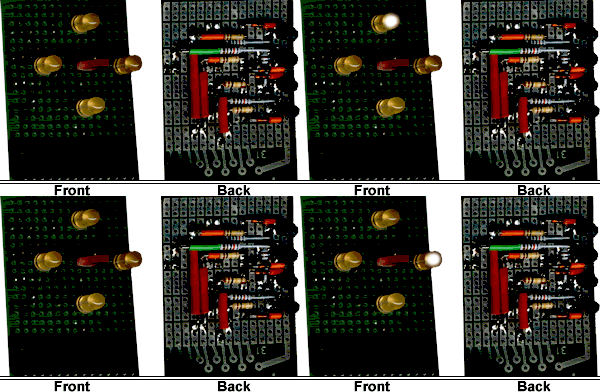
Because it is sometimes important to know if the system works well, I built a LED indicator, now you should know when the rotator has to turn hi.
LED Indicator and components ( see also above : "Original Version" )
In verband met enige vragen over het direct aansluiten van de LEDS :
Ondanks het feit dat de LEDS makkelijk kunnen worden aangesloten tussen bijvoorbeeld de 5 VOLT lijn en de collectors van de betreffende BC546B's met een voorschakelweerstand en eventueel een diode heb ik hier gebruik gemaakt van een aparte indicator omdat nu ook in de stand MANUAL de LEDS een seintje kunnen geven. Dit geeft aanzienlijk meer informatie ( afgezien nog van wat andere mogelijkheden ).

