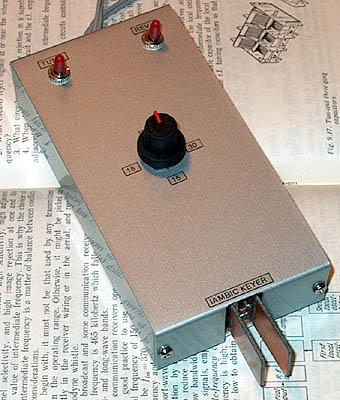
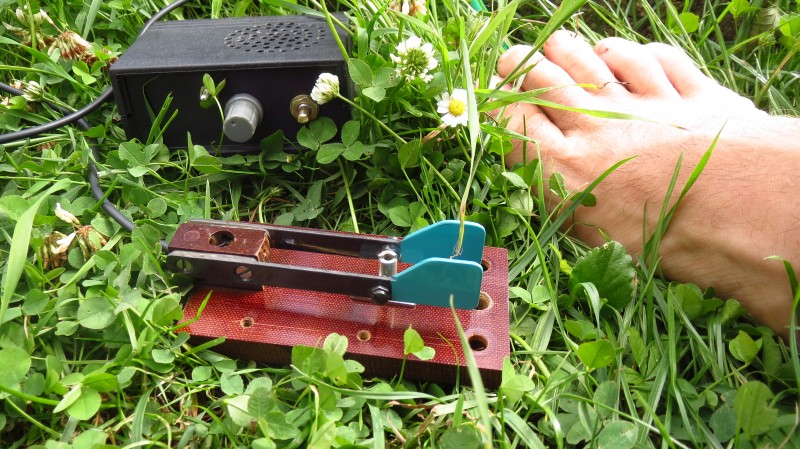
Iambic keyer with simple paddles and simple electronic circuit.
But using the keyer with my toes wasn't really a success!
SIMPLE IAMBIC KEYER
(1980 and 1999)
KLIK HIER VOOR DE NEDERLANDSE VERSIE
Iambic keyer with simple paddles and simple electronic circuit.
But using the keyer with my toes wasn't really a success!

Circuit diagram
Performance
It is a nice, simple keyer for QRP use. The supply current is 2.5 mA at 12 volt and only 0.7 mA at 5 volt.
When none of the two paddles is activated, the current is only 1uA! An on/off switch is even unnecessary! Four AA cells or a 9 volt battery is sufficient for hundreds of hours of use.
One minor point is that the dot-dash proportion is not exactly 1:3 but 1:2.8 and the dot-space proportion is not exactly 1:1 but 1:0.8. In practice this is not noticed however.
Speed adjustment
The speed is based on the specification that the dash is exactly 300ms at 12wpm. This can be measured with the use of an oscilloscope. For 15wpm, the dash is 240ms, 200ms for 18wpm, 150ms for 24wpm and 120ms for 30wpm (maximum allowed CW speed in The Netherlands).
The paddles
The paddles are made from pieces of double sided PCB and copper wire. The copper wire is used as contacts, as supports and as the hinge and spring. The parts you touch with your fingers are isolated for safety reasons. It is a simple construction but performance is good.
Another more modern solution is an old mouse. Only the switches are used, the electronic parts can be removed. The dot button is pressed with your forefinger, the dash button with your middle finger. After some practice, I could use such a mouse with success. Such a mouse is perhaps also a good solution for mobile use.
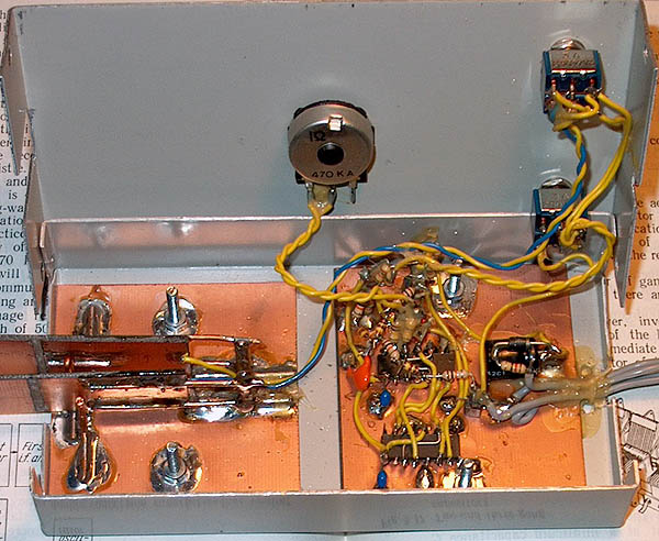
Internal view
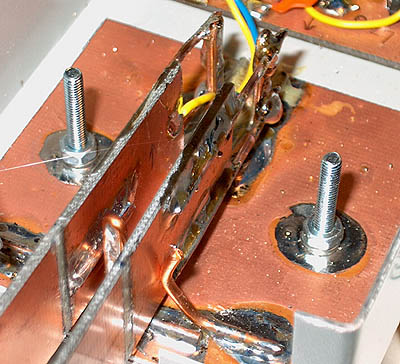
Detail of paddle made from copper wire 2.5mm2 and pieces of PCB
Center contact is ground and copper wires soldered on paddle are the other contact.
They are soldered to the yellow and blue wire. The parts touched with your fingers are isolated,
strips are cut away. Contact distance is adjusted by bowing the outer supports from copper wire.
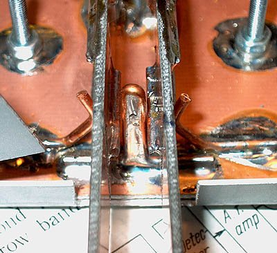
The copper wires at the back of the paddles are the hinge and spring, I took 1.5mm2 as 2.5mm2 was too strong.
Also very suitable for portable use during holidays!