LAZY FOOT ANTENNA
⚡ (2025) ⚡

The active Lazy Foot antenna, standard PVC pipes are used for the construction.
Size one foot, a simple circuit, a lazy design, so not the best performance.
The Lazy Foot Antenna!
The PA0RDT miniwhip antenna with HF isolation transformer works perfectly but needs a mains powered 12 volt supply.
I wanted a simple active antenna usable from 0.15 MHz to 30 MHz that can be used with the Bias-T voltage of a SDR receiver! The idea is that the SDR receiver and antenna can be operated with the laptop it's internal battery. Then it is possible to switch off the mains power in my house to see if a radio interferer is inside the house or not.
It is winter and only 8C degrees in my ice cold unheated workshop! Way too cold to go barefoot on the ice cold floor of my workshop! But shoes, socks and carpets are forbidden because of static electricity! So I had to go barefoot! My ice cold toes had even scary purple-red colors and were absolutely unable to withstand this horrible cold! Ice cold bare feet??? A foot is a nice size for the antenna! And a lazy project, I didn't want to put much effort into this project. A lazy project and the size of a foot, the Lazy Foot Antenna!
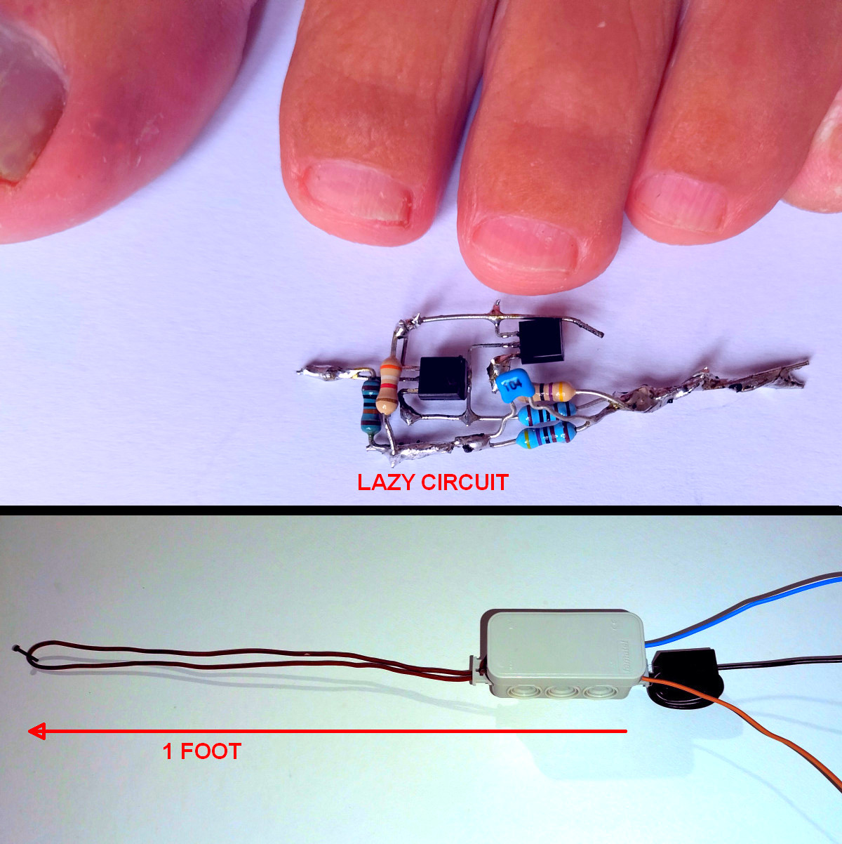
Prototype of the Lazy Foot Antenna. A Lazy designed circuit, and a size of one Foot!
The prototype!
The highest input impedance is needed at the lowest frequency of 150 kHz. The antenna wire of one foot has a capacitance of approximately 10 pF and that is an impedance of 100k ohm at 150 kHz. That is possible with a darlington circuit of 2 transistors, No FET with a very high input impedance has to be used! That makes the design easier. A FET can have different cut-off voltages. But a transistor has always a 0.6 volt base-emitter voltage. I had an idea, a simple circuit with two low frequency BC550 transistors! And this simple circuit does not need a Bias-T circuit that seperates the AC and DC supply voltage! I wanted to try that out! So simple, I did not need a PCB! And I was amazed! Excellent reception with the RSP1B SDR receiver! Just as good as the PA0RDT miniwhip! Even on 10 meters the natural background noise can be received! That was clearly visible when the antenna wire of one foot was disconnected! The frequency characteristic of the prototype was measured with the NanoVNA. The antenna was replaced by a 5 pF capacitor and... A perfect flat response upto 60 MHz! How is that possible with audio transistors?
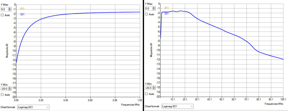
The frequency characteristic of the new improved version of the Lazy Foot Antenna
with extra attenuation of frequencies above 30 MHz.
New improved version
However, the performance on lower frequencies like the medium wave were much worse than the PA0RDT miniwhip. Very much noise... Till the power supply of the laptop was disconnected, then the interference was gone! So not the antenna, but the radio interference from the PC was the problem. The PA0RDT had an HF isolation transformer that suppresses the PC interference. But the simple prototype had some shortcomings. The supply voltage range was very limited between 4 to 6 volts. And it is a current source, it always needs to be loaded with a low HF impedance. Time for a new design and a simple construction for permanent outdoor use!
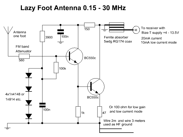
Diagram
The design
The active amplifier is not really an amplifier, it is more an impedance converter.
I was looking for excellent High Frequency transistors. TOTALLY WRONG!!! The capacitance of the one foot antenna wire is approximately 10 pF. At a low frequency of 150 kHz that is an impedance of 100k ohm. The input impedance of a SDR receiver is 50 ohms and that has to be converted by a factor 100k/50 is 2000x to that 100k ohm. But for 30 MHz the impedance of that 10 pF is only 500 ohm and the 50 ohm has to be converted to a just 10x higher value! So the most critical frequency is 150 kHz, not 30 MHz! We need a very good transistor for 150 kHz that still does something on 30 MHz! And that is the BC550, designed for low frequencies and low noise and good linearity! And it has a gain bandwidth fT of 300 MHz, that is 10 times higher than 30 MHz. So the darlington of 2xBC550 can still convert the 50 ohms with 10x to that 500 ohms at 30 MHz!
The 4 diodes form a stable voltage source of 2.4 volts. So there is approximately 1 volt across the 47 ohm emitter resistor of the second transistor, because there is also a little voltage drop across the 100k ohm resistor. That means that the amplifier can handle signals of 0.1 volt without any problems, maybe a little more.
The 150 ohm resistor and the 100 nF capacitor have two very important functions. They prevent feedback of the signal from the output to the input via the base-collector capacitance of the first transistor. It prevents unpredictable behavior. And there is always a minimum load of 150 ohms at the output of the circuit. This is important, this circuit is a current source, it always needs to be loaded with a low HF impedance. It is not a voltage source like the excellent and much better designed PA0RDT miniwhip!
The 560 ohm resistor at the input limits the frequency range to 30 MHz and attenuates strong signals from FM broadcast stations. But as you can see, the antenna has a flat frequency characteristic from 250 kHz to 30 MHz and is usable from 100 kHz or even 50 kHz. You do not need a high sensitivity at low frequencies.
The antenna is connected to the receiver with a thin RG174 coax of 15 meters. A ferrite absorber is placed at the antenna and two more wires are connected to ground as a counter pole.
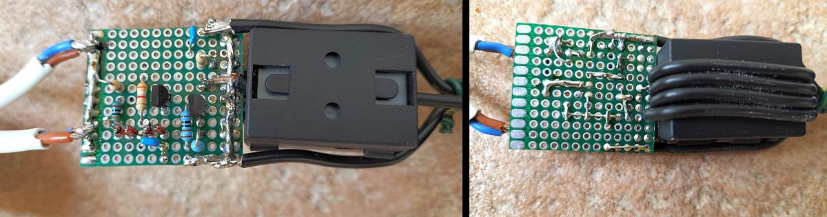
A simple construction on a standard PCB with holes
The construction
With way too cold bare feet and way too cold purple red toes on the way too cold tiled concrete floor of my workshop was a challenging experiment! It worked, no problems with static electricity! And still no broken toe joints... A simple antenna is not enough, we also need a simple construction! So let's continue with this exciting Lazy Foot Antenna project!
A simple construction on a standard PCB with holes. The size of the PCB and also the ferrite absorber just fits in the 4 cm PVC tube, but not in the 32mm tube of the support. So it's fixed at the bottom of the 40mm PVC tube of the antenna tube. The bottom of the 40mm PVC tube with antenna is glued to a 40mm to 32mm adapter. But is not glued to the support so that you can easily take it off. The ferrite absorber is not only an interference suppressor, but also the strain relief of the RG174 coax.
The construction with a PVC tube of 4 cm diameter and... one foot long!
A 40 mm to 32 mm adapter is glued to the bottom to mount it on the wall support.
The wall support made of PVC pipe of 32 mm and 45 degrees couplings. Two pieces of 25 cm
and one piece of 50 cm. The support is screwed to the wall with 7cm long 5mm screws.
The top cover of the antenna is not glued to the 40mm PVC tube so you can always take it off to access the antenna. And the antenna tube with 40mm to 32mm adapter at the bottom is not glued to the support either. The support is made from 32mm PVC pipe and 45 degree glued couplings are used so the cables can be easily pulled through. Two pieces of 25cm and one piece of 50cm, so you can use a 32mm piece of PVC tube of 1 meter long. The support is screwed to the wall with 7cm long 5mm screws.
WEBSHOP-LINK TO ORDER THE AWESOME LAZY FOOT ANTENNA!

I use 30 meters thin RG174 coax

Cable loss of 6 dB at 30 MHz but the antenna is still sensitive enough!
Almost ready!
We are almost ready! We have to add some ferrite absorbers. One ferrite absorber in the coax cable where it is connected to the receiver. I use cheap, thin RG174 low quality Chinese coax, no woven screen. Do 3 to 5 windings around the ferrite absorber. And if you have a long cable, longer than 10 meter or so, another ferrite absorber halfway the coax. They attenuate the higher shortwave frequencies, but are not so good at low medium wave frequencies. However, for the low frequencies we have another solution, the Bias-T supply box for the Lazy Foot Antenna with HF isolation transformer!

Almost ready, we have to add some ferrite absorbers for suppression of interference from your PC!

Attenuation of a ferrite absorber with 5 windings in a 50 ohm test setup.
Good at higher shortwave frequencies, but not so good at low medium wave frequencies

Perfect reception of weak QRSS signals on 30 meters!
Optional Bias-T supply box for the Lazy Foot Antenna with HF isolation transformer
Optional Bias-T supply for the Lazy Foot Antenna with HF isolation transformer
The Lazy Foot Antenna works perfectly with the Bias-T supply voltage of the SDR receivers. However, for frequencies below 3 MHz there is much interference from the PC, which is much lower when the laptop is disconnected from the AC power supply and uses the internal battery. But there are also receivers like the ATS20+ and the Navtex receiver that do not have a Bias-T supply. Then you can use this optional Bias-T supply.
But it does more, it is also a galvanic isolator and suppresses PC interference at the lower HF frequencies. If you use batteries for the Bias-T supply then there is no PC interference anymore below 3 MHz and it is possible use the AC power supply of the laptop without radio interference. Of course the Bias-T supply of the SDR receiver is not used then, but the batteries of the Bias-T supply box. I use 6 lithium batteries of 2000 mAh, that is 9 volts. So they have to be recharged every 100 hours.

Diagram of the Bias-T supply
The diagram
The isolation transformer consists of four twisted wires on an FT37-43 core. I used a different ferrite core type with similar characteristics because there are quite a few of them available here. The capacitors of 100nF and 22 ohm resistors are HF filters that suppress interference from the voltage source with at least 30 dB. The resistors are also a kind of fuse - current limiter for when there occurs a short circuit. A simple solution but they cause some voltage loss, approximately one volt. The output to the receiver has an extra 100 nF capacitor to prevent damage in case the receiver's Bias-T power supply is accidentally activated. The transformer in the Bias-T box causes some additional attenuation, especially at lower frequencies. However, at low frequencies, a lower antenna sensitivity is still sufficient. More turns cause less attenuation, for example, 8 instead of 4. But this will come at the expense of suppressing radio interference from the PC.

The Bias-T supply box interference attenuation. More than 50 dB at 1 MHz!
The Bias-T box frequency range

Bias-T supply in a wooden box with rechargeable batteries

Perfect reception of DL0BS with MFSK32 on 80 meters with MULTIPSK software!
Index PA2OHH