POOR MAN'S TCXO
(the simplest circuit on this website!)
(2021)
KLIK HIER VOOR DE NEDERLANDSE VERSIE
The simplest "Barefoot Technology" project on this website! Only 1 resistor!
Poor man's TCXO (the simplest circuit on this website!)
This is the simplest "Barefoot Technology" project on this website! Only 1 resistor!
We can greatly improve the frequency drift of a crystal oscillator with 1 resistor of 1/4 watt! Of course it is always better to use a real TCXO. But very often you cannot replace a crystal with a real TCXO.
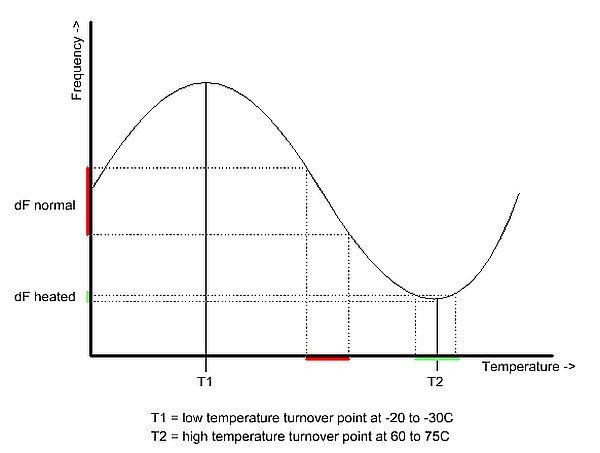
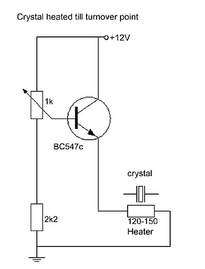
Temperature curve of a crystal when heated
How does it work
Very simple. We first will have a look at the temperature curve of a crystal. When we heat up a crystal, we see the frequency increase to the first turnover point T1. Then the frequency falls back to the turnover point T2. And then the frequency rises again until the crystal breaks.
At room temperature, the crystal acts on the slope in the graph, the red-colored part. And you can see that with temperature variations we have a considerable frequency variation (dF normal).
But we are going to heat the crystal to the turnover point T2 in the graph, the green colored part. And then you see that we have a much smaller drift (dF heated) with temperature variations!
All we have to do is heat the crystal to the turnover point T2! And we do that with a resistor of 1/4 watt!
A real "barefoot Technology" circuit of only 1 resistor!
The simplest circuit on this website.
How do we determine the correct value of the resistor?
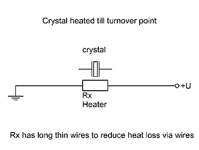
The resistor is glued to the crystal and connected to the standard power supply, usually between 5 and 12 volts. A guideline is that you need about 0.5 watts. But that is not possible, is it? The resistance is only 1/4 watt!!! However, that is not a problem. The resistor is glued to the crystal and cooled by the crystal. And can therefore have much more power.
We have to do the test at the average room temperature. So for example 21 degrees, then we can use the oscillator between 18 and 25 degrees.
We measure the frequency of the oscillator with a frequency counter. Or use an SSB receiver to listen to the pitch. For example, start with a resistor of 68 ohms and switch on the oscillator with heater resistor. The resistor and crystal will heat up. If the frequency only decreases during the warm-up, you are still in front of the turnover point T2. Now take a lower resistor, it takes more power and will therefore get hotter. For example 47 ohms. If the frequency of the oscillator first decreases and then increases again during warm-up, you are above the turnover point T2. Then we just take a default value between 47 and 68 ohms, which is 56 ohms. This is the correct value.
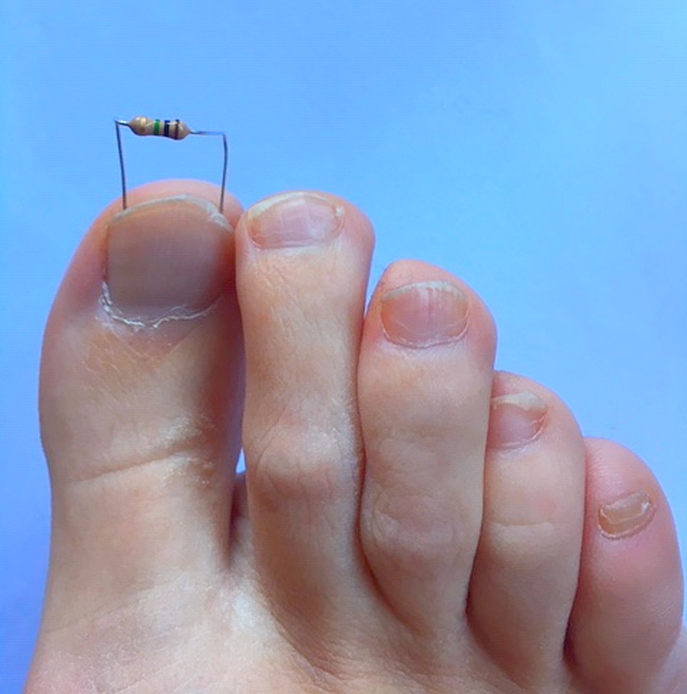
The heater resistor is glued to the crystal. Take long wires to
the resistor, then the heat loss due to conduction via those wires is less.
Assembly
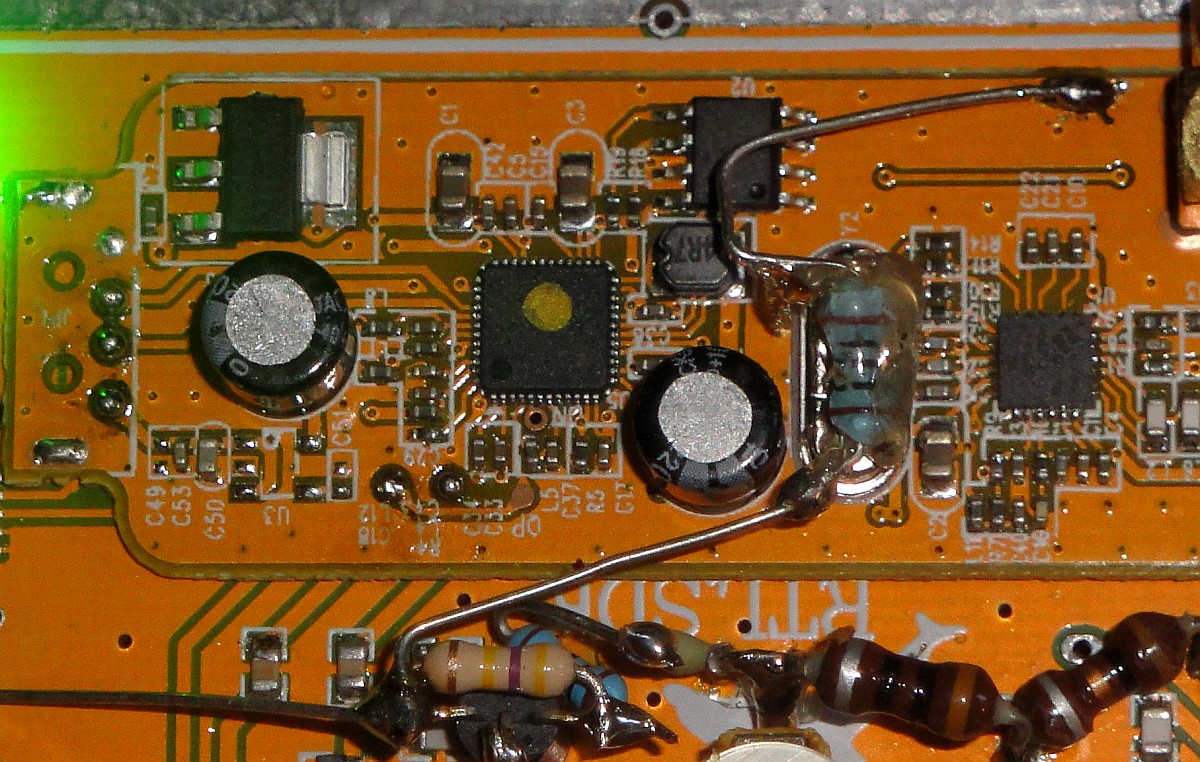
Above you can see an example. Take long wires to the resistor, then the heat loss due to conduction via those wires is less. And the resistor should be mounted on the bottom of the crystal, not on top. Because heat moves upwards. In this example you can see that the resistor is glued on top of the crystal. But... we turn this RTL.SDR dongle upside down during use, then the heater is at the bottom of the crystal!
You can glue the heater resistor onto the crystal with a glue gun or with whatever glue you want or have available.
Result
There is so much to say about a circuit with only one simple resistor!
For me, the RTL.SDR dongle was too unstable for QRSS reception. But with the resistor, the stability was at least 5x better. A disadvantage is that you cannot go too far above the turnover point, then the frequency drift of the oscillator becomes very bad.
Finding the right value is difficult. The test must be performed at the correct temperature. And the range is not that great, +/- 5 degrees around the average temperature or so.
My "radio lab" has no heating. During the winter it is only 8 degrees and I have to wear thick winter clothes. Then the stability is too bad, that is too far below the turnover point. And during the summer it is often 32 degrees in my "radio lab". That is too far above the turnover point. And above the turnover point, the frequency drift increases very quickly and is even more than without a heated crystal! So for me it only works in the spring and autumn, when the average temperature is about 21 degrees.
For my 80 meter QRSS receiver, a "luxury" version had to be developed for a wider temperature range.
LUXURY VERSION WITH ADJUSTABLE HEATER

Far too cold for the Poor Man's TCXO! At this low temperature
we use the "luxury" version with adjustable heater!
Horribly cold? At this low temperature we use the "luxury" version with adjustable heater!
It's only 8 degrees in my "radio lab"! It's way too cold for the Poor Man's TCXO! The temperature of the crystal is way too far below the turnover point! But there is a solution! The "luxury" version with an adjustable heater! We can control the heater with the help of a transistor and potentiometer. The low position 1 is for the summer. Position 2 for the colder autumn and spring and the high position 3 for the ice cold winter.
Still a true "Barefoot Technology" circuit!
Two resistors, a transistor and a potentiometer.
The emitter of the transistor follows the base voltage (minus 0.7 volts). The voltage is adjustable between approximately 65% to 100% of the supply voltage. Select the value of the heater resistor so that the turnover point can be set at all temperatures within the range of the potentiometer. I used a BC547, but any "standard" NPN transistor can be used.
It is now also very easy to set the temperature of the crystal at the turnover point. Turn the potentiometer up very slowly, the oscillator frequency will decrease. Then the frequency goes up again. The lowest point is the turnover point. Set the potentiometer to this position.

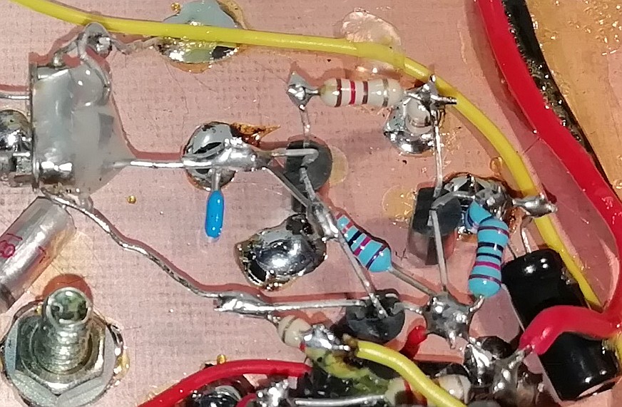
Long wires to the heater resistor to prevent heat loss by conduction through the wires.
Above you can see the circuit built into the 80 meter QRSS receiver. Long wires to the heater resistor to prevent heat loss due to conduction through the wires. And the heater resistor is glued under the crystal, heat moves upwards. The resistor of the transistor's emitter to ground has no function. It is used to hold the transistor.
Isolating the crystal and the heater resistor did not work. Even more power was needed with insulation material. So the insulation material cools the heater resistor!
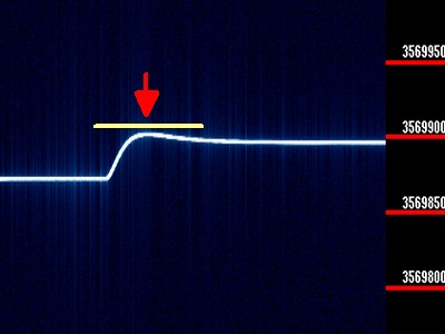
Turnover point adjustment with a QRSS receiver
The turnover point can be adjusted with a frequency counter or by listening to the signal with an SSB receiver. This can also be done differently for the QRSS receiver. Connect a calibration signal to the receiver. You will see a line on the QRSS screen. Turn the potentiometer and you will see the line rising, peaking and then falling again. Set the potentiometer to the peak, which is the turnover point.
VERSION WITH AUTMATIC CONTROL

Not an adjustable heater, but a LED that shows how the automatic control works.
This is still a fairly simple "Barefoot Technology" circuit!
The LED lights up quite brightly, because the heater has to heat the crystal considerably in this cold. It is often only 8 degrees in the winter in my "radio lab"! But much less energy is needed than with the first two circuits. This circuit works differently, it keeps the temperature constant. Not at the turnover point, but at a much lower temperature of about 40C degrees.
The advantage is that this solution is much more energy efficient. And it all gets much less hot. And it works without a manual setting, so no summer and winter mode! The temperature of the crystal is measured and regulated with an NTC resistor and a simple circuit with only three transistors.
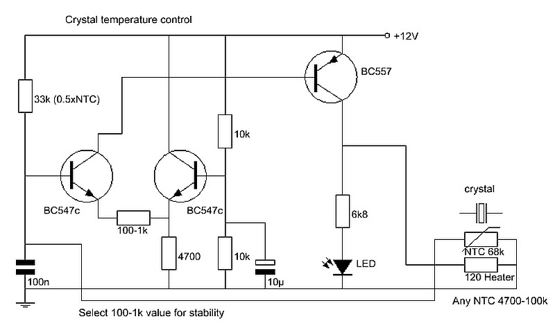
Still a fairly simple circuit! With an NTC resistor that measures the temperature.
No more heating up to the turnover point, this control keeps the temperature constant.
The two transistors BC547 form a differential amplifier. The base of the right transistor is set to half the supply voltage using the 10k ohm resistors. This is the switching point of the differential amplifier. The base is decoupled with a 10 uF capacitor. This was necessary, without this capacitor the circuit can start to oscillate.
The base of the left transistor is connected to the NTC resistor. If the value of the NTC resistor is higher than 33k, this transistor will activate the BC557 and the heater resistor will heat up. The 0.1 uF capacitor is for the decoupling of interference signals. If you have a different NTC resistor, take about half the value of the NTC resistor for the 33k resistor.
The gain of the differential amplifier is set by an emitter resistor between 100 ohms to 1k ohms. At a low value you have more gain and higher accuracy. But the control reacts very strongly and instability can occur. At a value of 1k ohm, the control is much smoother.
It is important that the NTC resistor is glued to both the crystal and the heater resistor with a thick blob of glue. The NTC must therefore make physical contact with both for a smooth regulation.
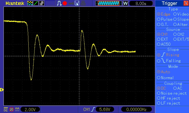
With a resistor of 120 ohms, the accuracy is better, but the response is very strong.
Switching on on the left, a temperature variation on the right by blowing cold air into the oscillator.

With a resistor of 1000 ohms, the accuracy is less, but the reaction less violent.
Switching on on the left, a temperature variation on the right by blowing cold air into the oscillator.

The circuit built into a VFO-BFO module with a SI5351 module.
The emitter resistor here is 150 ohms, which happened to be on the workbench.
The circuit built into the 40 meter QRSS receiver.
The emitter resistor here is 120 ohms, it just happened to be on the floor.
Results
You can see whether the circuit is working by the LED. In cold weather it lights up brightly, at 32C degrees very weakly.
It was 8C degrees in my "radio lab" and the LED lights up brightly. The VFO-BFO circuit was heated up until the LED was completely off, so about 40C degrees. The drift was about 1 PPM, or +0.5 PPM and -0.5 PPM. And this was a huge improvement. The module was totally useless for QRSS, but with this circuit, the stability is sufficient or at least good enough. There is drift due to aging, especially the first year. So calibration still has to be carried out regularly.
It might be that the stability is better when the control is operating at the much hotter turnover point. Then you have to replace the 33k resistor with an adjustment potentiometer and use it to adjust the temperature at the turnover point.
Of course it is better to buy a good TCXO. But there is none for the frequencies of my simple "Barefoot Technology" QRSS receivers...
Index PA2OHH