AGAIN COLD RECEPTION OF AUDIO FREQUENCIES
(2021)
KLIK HIER VOOR DE NEDERLANDSE VERSIE

This is NOT a radio but another simple "Barefoot Technology" project!
A real "Barefoot Technology" project
This project, the reception of audio frequencies, is another simple, sober "Barefoot Technology" project. Make a very simple audio amplifier, connect a 5 meter long antenna wire to the input and then see what you can hear with it! No high radio frequencies but just audio frequencies from 20Hz to 15kHz!
Receiving audio frequencies I had done before during my student days.

The simple idea of the audio frequency receiver.
The idea
The idea is simple. Connect an antenna wire to the microphone input of an amplifier and you will hear everything between 20 Hz and 15 kHz (audible audio range) being received by that antenna.
I wanted to repeat the reception of audio frequencies again. I now have the opportunity to try it much more extensively in a perfect, deserted location far from power lines and other 50 Hz power sources that can cause hum. And there needs to be a better, much smaller receiver instead of the old cassette recorder that I used the first time when I was a student! And I do not have that cassette recorder anymore, because you shouldn't collect too much junk in life.
It was not so easy to draw the schematic of the low-frequency amplifier in the radio.
Converting a radio from the flea market
I bought a radio at the flea market for only 1 euro. It was one from a rejected batch. When the high-frequency part is removed, it can be used for this exciting experiment. Then I have the housing, amplifier, volume control, battery holder, speaker and headphone connection for only 1 euro.
I was also curious how it is possible to make a speaker amplifier that works on 3 volts. Then you have to drive the output transistors completely open. How can you drive the power transistors completely open at that low voltage? I had already tried to design something like that myself, without success... Fortunately, there are smarter people in the world!
It was not so easy to draw the schematic of the low-frequency amplifier in the radio. But when you hold the print above a lamp, you can see the print paths as a shadow through the print on the component side. And the value of a capacitor had to be measured with a component tester.

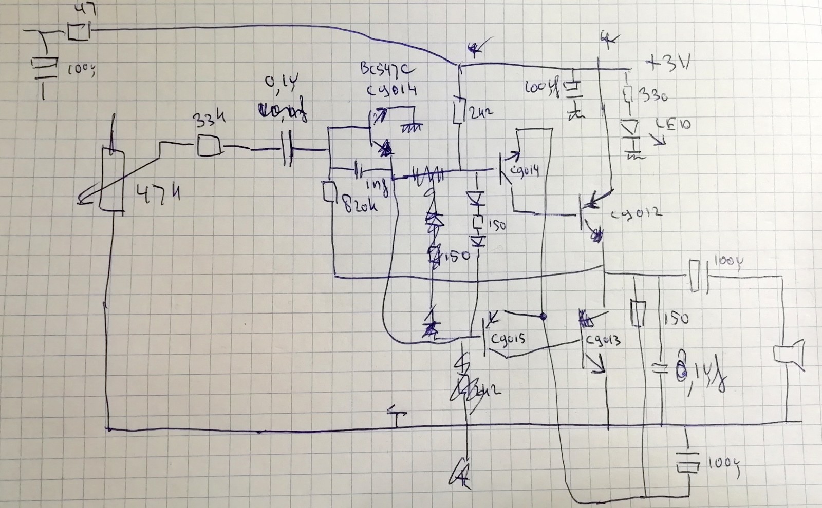
This is the design of the low frequency receiver
The design
An extra amplifier stage has been added to provide sufficient sensitivity. After the antenna input you will see a 1M resistor. This prevents the antenna from being statically charged. The 10k resistor and 1nF capacitor are a low pass filter. They suppress HF signals coming from the antenna. Without this filter, these signals are demodulated by the first transistor and you will hear all kinds of radio stations. The preamplifier is powered from the battery filtered by a 47 ohm resistor and a 100uF capacitor. These components were already in the original radio as a power supply for the chip.
After the volume control you see the original amplifier of the radio. The first stage is an amplifier. This transistor must have a fairly high current gain. If you want to use a BC547, take a type with a "C" as an addition, it has a higher current gain than the "normal" BC547. The capacitor between collector and base limits the frequency range. Adjustment of the base voltage is done by feedback from the output through the 820k resistor. The total gain is about 820k/33k or 24.84x.
This first stage drives the driver transistors. The two diodes 1N4148 with the 150 ohm resistor cause the control transistors to conduct slightly. You may want to omit (short circuit) the 150 ohm resistor.
Normally, the emitters of the driver transistors are connected directly to the output stage. But then the output transistors cannot be fully driven. By adding the 150 ohm resistor with the 100 uF capacitor, the driver transistors can fully drive the output transistors. The 100 uF capacitor keeps the emitter voltage about half the supply voltage! A clever design!

The construction
The construction
The HF chip, an LA1800 and all other HF components such as tuning capacitors, coils and ferrite antenna have been removed. The LA1800 is a nice chip with which you can make a very simple AM/FM radio.
The additional preamplifier is mounted on top of the PCB and glued. It doesn't have to be a perfect construction. This experiment will not be performed very often. Because let's be honest, who expects to hear something on audio frequencies with a few meters of wire as an antenna in a deserted place in nature!
The antenna connection is kept very simple with a terminal block. Make sure that the antenna wiring is as far away from the speaker output as possible. Otherwise the receiver may oscillate due to the coupling between the input and output wiring.
The reception results
When you hold the terminal block against certain devices, such as a monitor, you will already hear strange signals. Except for the hum everywhere, I hear a ticking every half second in the house, but I don't know (yet) what it is. And even with the terminal block against a digital watch I can already hear strange signals. With an antenna you would only hear 50Hz hum from the mains in the house. So we have to find a deserted place, far from buildings, power lines and other power lines. I have a nice place here without curious passers-by!
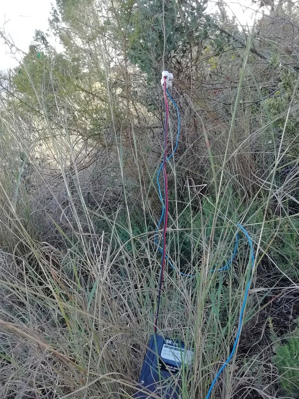
The antenna wire thrown in the tree over a branch.
Exciting! What do we hear?
Attempt 1
Not a very good place. Many nests with processionary caterpillars and stinging bushes. Very uncomfortable.
I didn't hear the creaking I had heard before. But all short clicks. Unfortunately there was too much wind. The antenna was moving too much and the wind was making too much noise. And the receiver acted strange, when we got home it turned out that the spring of the battery holder did not make good contact with the battery. And it started to rain... But that's okay, I'll try it again soon! You shouldn't stop an experiment if it doesn't go well in the beginning!

Another place, cold cloudy weather with low hanging clouds. And...
Enough stones to throw the antenna wire over a branch!
Attempt 2
A much better place and a fantastic tree! Barefoot to avoid static electricity. Because that static electricity might have been the cause of that crackling last time!
Everything was good. No rain and little wind so the antenna didn't move. There was a lot to hear! Many burst of short loud crackles! Very loud clicks and weaker prolonged crackles, probably from distant thunderstorms 200 km away. The receiver was now working fine! The experiment was successful! Horribly cold toes because it was very cold weather!
But then there will be new questions. Those loud clicks, are they perhaps electrostatically charged flies hitting the antenna or the tree branch? Or do I receive the crackling of my brain?

Find the antenna wire in the tree!
New plans
I need to make a new receiver. Next year. No wire antenna but a shorter whip antenna and a high-impedance FET input. Because throwing a wire with a stone into a tree is not that easy... Then it is much easier to find a suitable place, far from civilization and electricity pylons. On a mountain top for example! To be continued next winter!
Index PA2OHH