ATS20+ RECEIVER WITH Si4732-A10 CHIP
(2021)

How is the performance of this simple and cheap ATS20+ receiver with Si4732-A10 chip?
Barefoot with way too cold toes on the much too cold tiled floor to find that out...
ATS20+ receiver with Si4732-A10 chip
George did not like the ATS20+ receiver. He used a GOOD antenna instead of a RIGHT antenna and I wanted to prove that I was RIGHT! A GOOD antenna is not always the RIGHT antenna for this receiver!
Winter and only 8C degrees in my ice cold workshop but barefoot on the way too cold tiled floor to prevent static electricity that can easily destroy the vulnerable antenna input of the ATS20+ receiver! Way too cold for my bare feet and my toes were absolutely unable to withstand this horrible cold! We are afraid that this project will end with broken toe joints due to the cold!

Rear view
I was really surprised!
George knew for sure that I wouldn't like the ATS-20+! Indeed, I expected very little from this simple and cheap receiver. Many comments on the internet said that it was worthless crap that should be thrown in the trash immediately! A receiver without coils, without HF band filters, without crystal filters, no variable tuning capacitors, just one little chip!!! However... I was really surprised! The receiver performed much better than I had expected with the supplied whip antenna! Why did others have such bad experiences? Perhaps that I know the reason! They did not read the Advisory Notes AN332 and AN383 of the manufacturer of the chip!
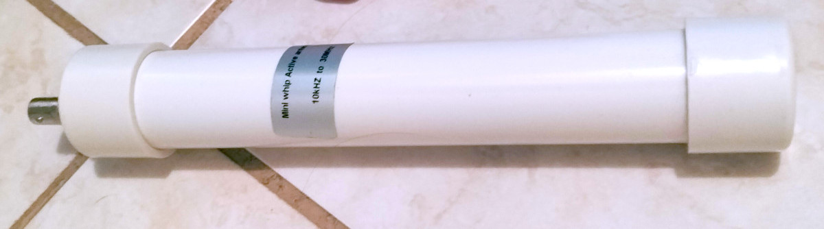
The PA0RDT active mini whip! Believe me, this little antenna is much better suitable for the ATS20+ than a long wire antenna!
This receiver needs a special antenna!
The reason why George and other people have such bad results is that this receiver needs a special antenna. A GOOD antenna is not always the RIGHT antenna for this very sensitive receiver!
The Advisory Note AN383 gives important information about antennas that you can use. Only whip antennas with a maximum lentgh of 60 cm! Many people do connect this receiver to their outdoor long wire antenna and such an antenna is much longer than 60 cm! The antenna input is connected directly to a pin of the Si4732 chip and it will be overloaded by the strong signals of such a long wire antenna. And that is the reason why people find it a bad receiver! And... you can wait for the day that the chip will be damaged by Electro Static Discharges or sparks during thunderstorms or static electricity during rain- or hailstorms with such an outdoor long wire antenna!
You have to use the right antenna!
The PA0RDT mini whip for example and no long wire antennas!
I found the PA0RDT active mini whip antenna!
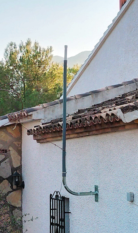
Of course, you have to use an outdoor antenna for serious reception results. Indoors with the supplied whip antenna the signals are weak and the interference levels are high! I found the PA0RDT active mini whip! It has a not too high output signal, but enough for a perfect reception, so the output signal of the active whip antenna does not overload the input of the receiver. It has a flat frequency response. It is protected by a non-conductive enclosure against ESD, sparks and other electric discharges, the receiver will not be damaged! So a perfect outdoor antenna for the ATS-20+ receiver!!!
Diagram
Let's take a quick look at the diagram first! A chip, the antenna is directly connected to the AMI pin 8 of the chip via a capacitor! AM, SSB and FM reception, stereo and RDS! I have the "+" version, it has an extra 76 to 108 MHz bandpass filter with HF preamplifier for the FM band.

The simple diagram!
Incredibly, the ATS20+ performed much better than expected!
The ATS20+ is connected to the PA0RDT active miniwhip antenna and I was amazed! Perfect reception of the Long Wave Broadcast transmitters! I could listen to Radio 4 at 198 kHz at a distance of 1500 km! It is nice that you can select bandwidths of 3 kHz and 4 kHz! And many radio beacons between 250 kHz and 400 kHz could be received! A perfect reception of many Medium Wave Broadcast transmitters. And... on all radio amateur bands upto 30 MHz it was a pleasure to listen to SSB and CW stations! Also digital signals could be heard. For SSB you can select low pass filters of 2.2 and 3 kHz. I prefer 3 kHz. And for CW there are low pass filters of 3 kHz, 2.2 kHz, 1.2 kHz and a bandpass filter of 1 kHz with a center frequency of 1 kHz and a bandpass filter of 500 Hz with a center frequency of 750 Hz. For CW I prefer the 2.2 kHz low pass filter.
The sound is very good for such a simple little radio! The AVC (Automatic Volume Control) works perfectly. I prefer a setting of 60 but can imagine that you want to use a lower setting of 50 or 40. Try it yourself!
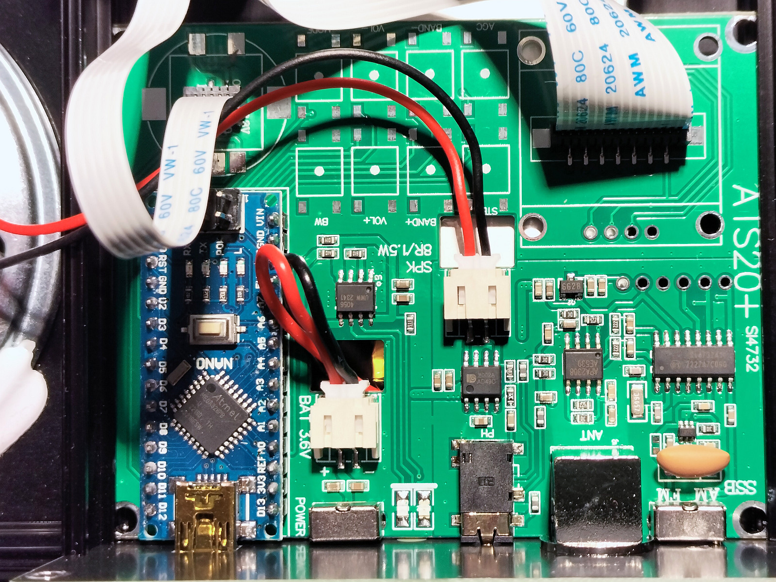
Very simple, no tuned circuits and no adjustment points! At the left the simple and cheap blue
Arduino Nano processor board that controls the receiver and can be programmed with your own software!
A few shortcomings had to be solved!
At first I did not notice any effect of the AGC (Automatic Gain Control) and AT (Attenuator) setting. But on the long wave and medium wave, I had a less good reception when an "AT" (attenuator) setting of less than 10 dB was used. But the automatic setting of the ACG performed very well. At the left you can see the simple and cheap blue Arduino Nano processor board that controls the whole receiver. It can be programmed with your own software. And that was necessary, there were a few shortcomings that were important to me.
It was NOT possible to receive the Navtex frequency of 518 kHz and not all shortwave frequencies. There were gaps between the various shortwave bands! But it is easy to modify and upload software, I changed the bandplan table to solve this problem. I discovered that it was not possible to tune the chip lower than 150 kHz for 77.5 kHz DCF reception. That was not a problem, just an experiment, I like experiments!

The new bandplan table and the Arduino IDE that is necessary to modify the software in the Arduino Nano board.
Great! I can modify the software!
With way too cold bare feet and way too cold purple red toes on the way too cold tiled concrete floor of my workshop was a challenging experiment! It worked, no problems with static electricity! And still no broken toe joints... So let's continue with this exciting ATS20+ project!
It is possible and not difficult to modify the software! The software in the receiver is based upon the library of Ricardo Caratti (PU2CLR) and various software versions for the receiver can be found on his Github page:
See: https://github.com/pu2clr/SI4735/
And he also describes how to upload new software:
See:
https://github.com/pu2clr/SI4735/tree/master/examples/SI47XX_KITS/AliExpress
I use a modified version of: "SI473X_ALL_IN_ONE_OLED_RDS_CHINESE_V8r".
Important is to select the right Arduino Nano with the Old Bootloader, the "ATmega328P (Old Bootloader)"!
Replace the directory with that version with my version here below if you want that.
Just connect the USB port of your PC with the USB mini connector, not the C type. It works, even if the receiver is switched off!
Link to download the ZIP file with my modified version "ATS20PLUSPA2OHHV1"
I wanted to keep the modifications as simple as possible, so not perfect!
The bandplan table was modified as you can see on the picture here above.
The data is saved after 10 seconds when you do not change something. When switched on, this data is loaded from the EEPROM. I changed that 10 seconds to two hours. Otherwise all kinds of uninteresting frequencies will be stored in the EEPROM and will overwrite the interesting ones! And after that the data is stored, the Arduino Nano board goes into sleep mode. The processor and its internal oscillators will be switched off. It will not cause any radio interference anymore and use less power. However, the receiver continues to work at the same frequency with the same settings. You have to switch the receiver off and on to activate the processor. Or rotate the encoder works too, the ATmega goes out of sleep mode when certain pins are activated.
The BFO steps of 10 Hz and 25 Hz were increased to 25 and 100 Hz. And when you tune the BFO, the RF frequeny steps automatically 1 kHz up or down. Now it is possible to tune through a whole segment of an amateurband with 100 Hz steps.
After 10 minutes, the display goes now into sleep mode. Interesting if you use it for very long monitor periods on one frequency!
And some step sizes and settings have been changed to my personal preference.
New button functions of the modified version "ATS20PLUSPA2OHHV1"
BAND+
Short press: Band selection with rotary encoder
Long press: Band up
VOL+
Short press: Volume control with rotary encoder
Long press: Volume up
STEP
Short press: Tuning frequency step size with rotary encoder
Long press: Change tuning frequency step size
AGC
Note: AGC is automatic Gain Control, AT is a fixed attenuator setting
Short press: AGC or attenuator setting with rotary encoder
Long press: Change AGC or attenuator setting (changes up-down after next long press)
BAND-
Short press: Soft Mute with rotary encoder (a kind of noise reduction for AM reception)
Long press: Band down
VOL-
Short press: Automatic Volume Control setting with rotary encoder
Long press: Volume down
BW
Short press: Bandwidth setting with rotary encoder
Long press: Change bandwidth (changes up-down after next long press)
MODE
Press: Change AM - USB - LSB mode
ROTARY ENCODER
Press: Change VFO tuning - BFO tuning
More exciting experiments!
Is it possible to receive Navtex on 518 kHz? And Digital Selective Calling at 2187.5 kHz and 8414.5 kHz?
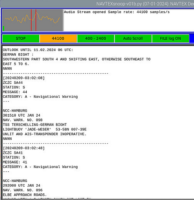
Perfect Navtex reception, even without a selective HF bandfilter of 518 kHz!
Navtex reception
A perfect Navtex reception, even without a selective HF bandfilter! The same stations can be received as with my normal shortwave receiver!
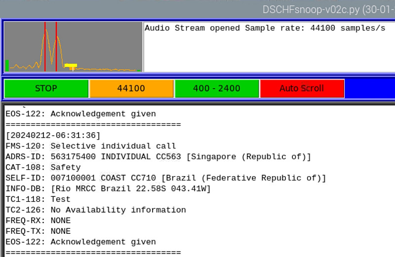
Perfect reception of Digital Selective Calling!
Digital Selective Calling reception on 8418.5 kHz
A perfect DSC reception, even without a selective bandfilter! The same stations can be received as with my normal shortwave receiver!

QRSS reception failed!
QRSS reception on 10 MHz (30 meter amateur band)
We finally found the limit! For QRSS reception we need a very temperature stable frequency and an extremely low frequency jitter. The frequency jitter is too high as you can see on the picture above and also the frequency drift due to temperature variations is too much for QRSS.
Conclusion
The ATS-20+ is a very nice cheap simple receiver with very acceptable performance if you use the RIGHT antenna! It can be used for the reception of traditional digital modes like Navtex and DSC. But the frequency jitter and stability are not good enough for QRSS. Barefoot on that way too cold stone floor during many weeks of this ATS20+ project was an exciting experiment! Terribly cold suffering toes with scary purple-red colors! George and I are amazed, no damaged toe joints! Next winter colder please!!!
Index PA2OHH