QRSS RECEIVER FOR TWO BANDS
(2020)
KLIK HIER VOOR DE NEDERLANDSE VERSIE
The old direct conversion QRSS receiver is replaced by two simple receivers with sideband suppression
in a low-budget wooden box with transparent lid. Now 10 and 20 meters can be received at the same time!
Two new QRSS receivers for 10 and 20 meter meters
The old direct conversion QRSS receiver works fine. But it has no unwanted sideband suppression and receives both sidebands, so also the unwanted ones!!! And the 10 meters and 20 meters band cannot be received at the same time. So it was necessary to make two new single sideband receivers in one housing. The unwanted sideband is suppressed and also the noise of that side band. That is why the sensitivity is also slightly better.
Of course it should again be a simple "Barefoot Technology" radio project, even so simple that it is suitable for a poor, modest and sober living barefoot monk!
A single SI5351 module with an Arduino Nano should generate the VFO signal for both receivers. Two is the maximum, although there are three clock signal outputs!
The 80 and 40 meter QRSS receivers have proven that the simple principle applied here works. But is phase suppression on the high 10 meter band frequency still possible? That is asking for trouble or rather, begging for challenges!
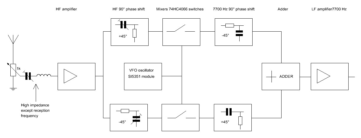
The principle of the sideband suppression
The principle of the sideband suppression
The unwanted sideband is suppressed by the phase method. The 90-degree phase difference in the high-frequency part is realized by the two 45-degree phase networks with a trimmer for optimal adjustment. And in the low-frequency part there are also two 45 degree phase networks to realize the 90 degree phase difference. As a result, one sideband is suppressed by the substraction of both signals and the other is amplified by the addition of both signals.
But the phase difference must be 45 degrees over the entire low-frequency range! This requires quite complex circuits and we don't want that! We want simple, sober "Barefoot Technology" radio projects! We want to use a low-frequency phase network with only one resistor and one capacitor! With such a simple network, the phase difference is accurate enough in a region of 5% around the center frequency. If we take the usual 1500Hz it is only 75Hz and that is too little. The QRSS bands are 200Hz to 300Hz wide and even more at 10 meters! But of course there is a simple "Barefoot Technology" solution! When we increase the frequency of the low-frequency output signal of the receiver to 8000Hz, then that 5% band suddenly becomes 400Hz and that is more than enough!
Here 7700Hz is chosen as the frequency, because there is a disturbing signal at 8000Hz and my cheap audio cables have great difficulty with that... But you can use any frequency between 7000Hz and 8000Hz. Just adjust the output frequency of the SI5351 oscillator module!
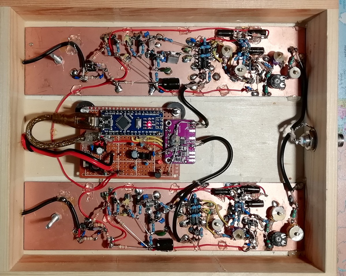
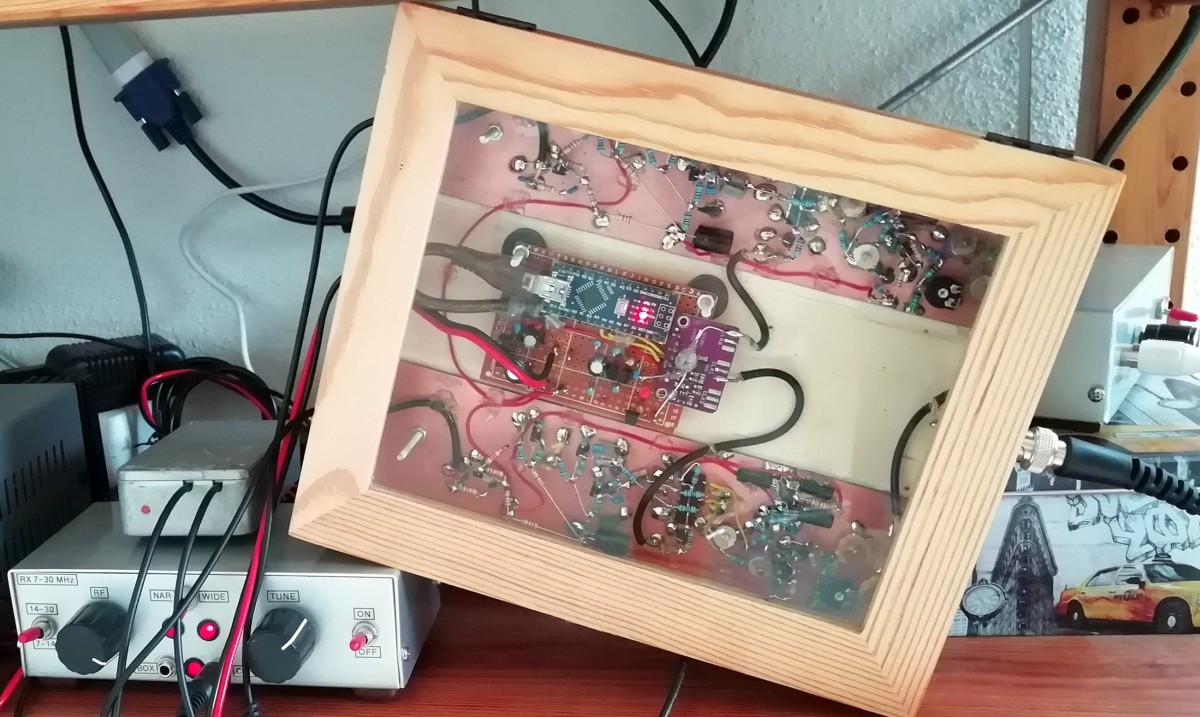
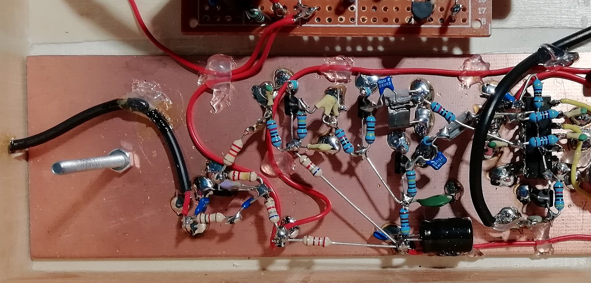
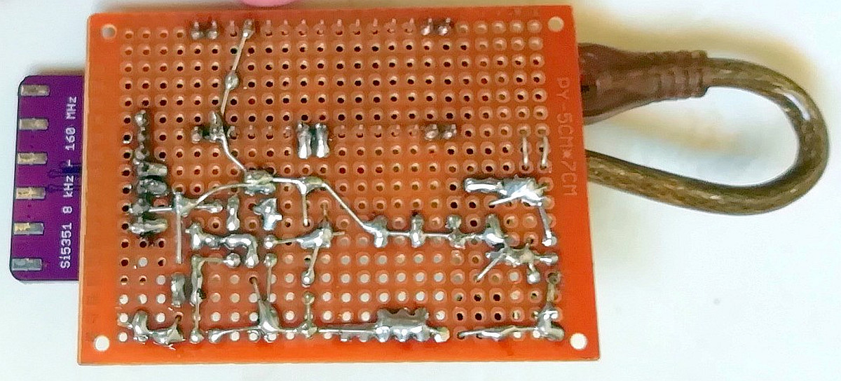
Another challenging and simple "Barefoot Technology" radio project! In a simple wooden box!
Two QRSS receivers and a very cheap module with the SI5351 clock oscillator that controls both receivers.
HF amplifier
At the input is a 1k ohm potentiometer, with which the sensitivity of the receiver can be optimally set and overloading by strong signals can be prevented.
But why is there a series resonant circuit? It is tuned to the receiving frequency and has a low impedance only for that frequency. For other frequencies this is a high impedance. So you can connect multiple receivers for different frequencies to the same antenna without attenuating each other's signals!
After this series circuit you can see the tuned circuit consisting of two coils and a trimmer. This selective circuit allows only a small band to pass around the receiving frequency and attenuates the unwanted signals on other frequencies. You can also compose the value of a trimmer from a parallel circuit of a capacitor and trimmer with a smaller value.
Due to the high emitter resistance of 470 ohms, the first transistor has a high input impedance. It will not attenuate the tuned circuit much. The capacitor with a small value of 10pF and the resistor of 1k ohm protects the transistor a bit from high voltage peaks and the resistor also prevents the RF amplifier from oscillating. The second transistor has a low-impedance output, which is necessary to drive the phase networks. And both transistors and also the tuned selective circuit amplify the signal.
The design is usable on all frequencies. For frequencies lower than 14MHz you can use a BC547 instead of a BF494. And for 10 meters I connected an extra 470 ohm resistor in parallel with the 470 ohm emitter resistor for some extra gain.
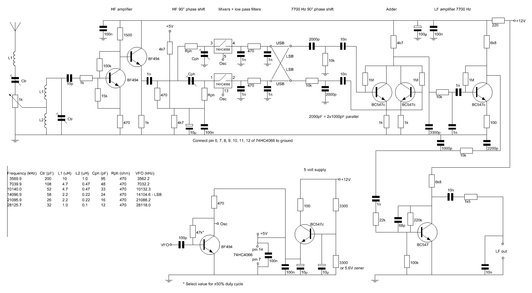
Schematic diagram, almost all transistors! Some explanation is needed to understand everything!
High frequency phase networks
After the HF amplifier, the signal is split into two signal paths. A 90 degree phase difference must be realized using phase networks. The 470 ohm trimmers and resistors do this. With the trimmers you can optimally adjust the phase so that the suppression of the unwanted sideband is maximized. One phase network is at -45 degrees and the other at +45 degrees, the difference is then 90 degrees. And does one signal path need a little more signal and the other a little less? Then you adjust one trimmer to -50 degrees and the other to +40 degrees. So the trimmers not only adjust the optimal phase, but also the optimal amplitude!
If the low-frequency phase networks do not differ exactly 90 degrees, you can correct this with the trimmers. Then the phase difference in the high frequency phase networks is a little less or more than 90 degrees. You will not notice that the reception sensitivity decreases slightly and is probably not even measurable!

High frequency part
Mixers
My QRP sets usually have a 74HC4066 as a receiver mixer. A simple, cheap solution and it works fine, no audio detection from strong broadcast stations and great sensitivity. So it makes sense to use those mixers now too, there are still a number of unused ones here! But you can also use a better, more modern FST3253 chip.
The mixers are semiconductor switches that are switched by the signal from the SI5351 module and the subsequent transistor amplifier. The IC 74HC4066 contains four of those switches, we only use two. A disadvantage is that also HF signals and audio frequent signals are passed from the input to the output. For example noise on audio frequencies from the HF amplifier. But the high-pass filter right after the HF amplifier consisting of a 1000 pF capacitor and a 470 ohm resistor allows only HF signals to pass and blocks these audio-frequency signals.
The voltage divider with two 4700 ohm resistors sets the mixer input to approximately half the voltage.
After the mixers you will see low-pass filters, each consisting of two 1 nF capacitors and a 470 ohm resistor. This filter allows only low-frequency signals to pass and blocks HF signals coming from the HF amplifier. This prevents detection of strong AM broadcast stations in the audio amplifier.
Low frequency part
Low frequency phase networks and the adder
The low-pass filters are followed by the two low-frequency phase networks. These are the 2000pF capacitors and 10000 ohm resistors, a very simple network! You can make a 2000pF capacitor by connecting two 1000pF capacitors in parallel. One phase network rotates the phase with -45 degrees and the other with +45 degrees, the difference is then 90 degrees. And it doesn't have to be very precise, it's not necessary to use very accurate components. If the difference is not exactly 90 degrees, no problem! You can correct this with the trimmers in the high-frequency phase networks. You will not notice that the reception sensitivity decreases slightly and it is not even measurable! If you want to use the low sideband, you have to use the "LSB" connections, for the high sideband the "USB" connections.
The signals from both networks must be added together. This happens in the circuit with two transistors and a common 4700 ohm collector resistance. The 1k ohm emitter resistors convert the input voltage into a current and the two currents are added together in the 4700 ohm resistor and converted back into a voltage. You don't have to use "paired" transistors with identical gain. The circuit also amplifies a bit: 4700 ohm / 1000 ohm or 4.7x.
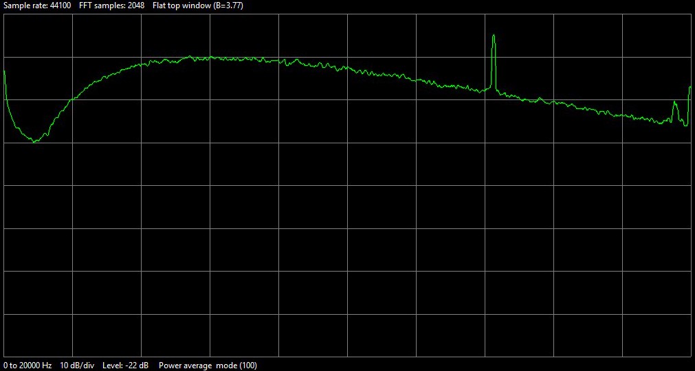
The frequency curve of the low-frequency amplifier, measured with noise.
An audio frequency between 7000Hz and 8000Hz is perfectly usable
Low frequency amplifier
And then there are two more transistors, the low-frequency amplifier. The first transistor has an emitter resistance of 100 ohms and a collector resistance of 6800 ohms. Due to the 100 ohm emitter resistance, this stage has a high input impedance and a considerable negative feedback, so that practically no distortion occurs. The gain is again about 6800 ohms / 100 ohms = 68x.
The last stage also has quite a bit of feedback. At the base is a 22k ohm resistor and between the collector and base is a 220k ohm resistor. The gain is 220k / 22k = 10x. The 100k ohm resistance to ground ensures the correct DC bias setting.
The various capacitors to ground and the 68pF capacitor attenuate the high frequencies. The 1k5 resistor at the output ensures that the output stage is minimally loaded with that 1k5 impedance and is also a protection if you connect something crazy to the output. The last capacitor is an extra low pass filter with the 1k5 ohm resistor. Costs almost nothing and makes a difference.
The last stage has a lot of negative feedback. Therefore, the output impedance is equal to that 1k5 ohms. It should be low enough to load the audio cables. Otherwise the cheap audio cables will pick up too much interference from the environment!
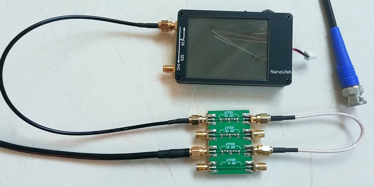
The sideband suppression was measured with the NanoVNA of 50 euro and a program to use it as a sweep generator.
The output level is controlled with an attenuator module of 8 euros. And you can check this attenuator
with the... NanoVNA! Everything low-budget, but you can measure a lot with it!
Supply
The 220 ohm resistor, capacitors and 100nF capacitors are decoupling capacitors for the power supply to filter out interference signals. And then there's a 5 volt power supply with a simple transistor. This is the supply voltage for the 74HC4066 and the oscillator. I didn't have a suitable zener diode. But the base has 6 volts, so the emitter is about 5 volts. The 100 ohm resistor in the collector is a current limiter, useful if you accidentally make a short circuit!

The SI5351 oscillator module with temperature stabilization
The SI5351 module!
And then the most important part, the oscillators for the mixers! There were no useful standard crystals for sale. But a cheap SI5351 clock oscillator module with an Arduino Nano could be a great solution!!! Unfortunately not as simple as a crystal oscillator, but also not very difficult and very interesting! How does such a module work? And software has to be created! But then you also have a great, general purpose oscillator. This one can also be used for other frequency bands! Simply program a different frequency and change a few inductances and trimmers in the receiver!!! So this QRSS receiver design can easily be used for other bands too!
But how should you program an Arduino Nano? And how can you control such a SI5351 module? No idea! I thought it would be great to experiment with it intensively for a few challenging weeks!
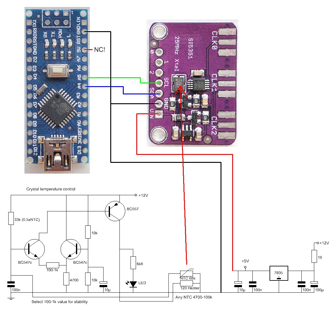
The schematic of the SI5351 oscillator module. Only two low-jitter CLK outputs can be used simultaneously
because the SI5351 module has only two PLLs. For these receivers, these are CLK0 and CLK1.
After a few weeks it was completely clear to me how to program the Arduino Nano and how to control the SI5351. There was an SI5351 library, but it programs the fractional dividers instead of the PLL frequency. And that creates much more jitter. Only two low-jitter CLK outputs can be used at the same time because the SI5351 module has only two PLLs. For these receivers these are CLK0 and CLK1. There was a special bit that had to be set when using this mode. And you have to turn off unused outputs, the example programs on the internet didn't do that! Very exciting and fun to study all of this! I had made software for the oscillator module!

Programming the Arduino Nano. Load the program "GRABRX01.ino"
and press the arrow symbol just below "edit" to upload it.
Software for the Arduino Nano
It was a nice challenge to make my own program: "GRABRX01.ino" which you have to upload in the Arduino Nano!
When the Arduino Nano is started, it sets the frequencies of the CLK0 and CLK1 outputs. Then the command "set_sleep_mode(SLEEP_MODE_PWR_DOWN)" is given. This disables all internal oscillators of the Arduino Nano, so that it can no longer cause radio interference! If you want to use the SI5351 module for other frequencies, you have to change them in the program.
In normal use, the Arduino Nano is powered from its own 5 volts via the short cable. After a power failure, it reboots and programs the SI5351 and then goes into sleep mode. When you want to program the Arduino Nano, disconnect that short cable and connect the Arduino Nano to your PC.
In the ZIP file "20qrxdcsource.zip" you will find the program "GRABRX01.ino" that you have to upload in the Arduino Nano.
Programming the Arduino Nano is not difficult! You can find everything at https://www.arduino.cc/ under the downloads. And there is much more information about the various Arduino versions.
Download and install the IDE. Connect the Arduino Nano to the USB port of your laptop or PC and at "Tools - Port" you can select the correct COM port. When it works, you've got the right COM port.
With "File - Open..." you open a program, which is a file with the extension ".ino". You can check a program for errors with the first V on the toolbar. With the second round with arrow the program is compiled and uploaded and then you are done!
A program consists of two parts. The "void setup()" section contains the configuration, for example which ports are configured as input or output. The second part "void loop()" contains the program. More information can be found on the Arduino website mentioned above.
The result is an SI5351 module with crystal oven for the universal QRSS receiver!
Crystal oven
Yet there is still a problem!
For QRSS reception, the oscillator must be very stable. A drift of less than 1 Hz per hour is desirable. And also an absolute accuracy of 5 Hz. An ordinary crystal oscillator is not stable enough, there is too much frequency drift due to temperature variations. The crystal is kept at a constant temperature by a "heater" resistor and an NTC resistor as a temperature sensor. The two transistors BC547c form a differential amplifier. The output drives the BC557 driver transistor for the "heater" resistor. Choose the emitter resistance of the left transistor BC547c in such a way that the circuit does not oscillate and also does not show too many wobbles. You can see this from the LED. I'm using a 120 ohm resistor. When switching on, oscillations are normal, but they should die out fairly quickly to create a stable situation.
The "heater" resistor is soldered and glued directly to the housing of the crystal, as well as the NTC resistor. It is very important that the NTC resistor makes good physical contact with the heater and also with the crystal. The NTC resistor must be heated up as quickly as possible by the "heater" resistor. As a result, the heating of the crystal will be slow and the circuit is stable. And everything is glued together by a thick blob of Glue stick glue, which you can melt with your soldering iron. This blob also provides a delaying warm-up effect and a quieter control.
SI5351 modules are also available with a TCXO. That is of course an easier solution! And what is the best solution? A TCXO that is kept at a constant temperature with this temperature stabilization!

The simple GPS frequency is used as standard for adjustment.
Adjustment
The GPS frequency is used for the adjustment. You can find the description on this website. The frequency can be set to any value between 1 Hz and 10 MHz, even a few MHz higher with reduced quality. The low frequency output is connected to the audio input of the PC and an audio spectrum analyzer program (there are many) is started on that PC. The GPS frequency standard is connected to the antenna input via a high-impedance resistor or a "pick-up" wire. Set the frequency of the GPS frequency to the QRSS frequency. Adjust the trimmers of the input circuits to maximum. You can vary the level of the test signal with the 1k attenuator potentiometer.
Now comes the difficult part, adjusting the sideband suppression, that will keep you busy for a while!
Set the frequency of the GPS frequency back to the QRSS frequency and adjust the signal with the 1k attenuator so that the signal is at the top of the spectrum display. Read the audio frequency. With my receiver it is 7700Hz. Then set the frequency of the GPS frequency to the unwanted sideband, that is QRSS frequency - 2x the read audio frequency. So for me that is: QRSS frequency - 2 x 7700Hz. For LSB reception, that frequency is QRSS frequency + 2 x 7700Hz. Now you will see a weaker signal in the exact same place in the spectrum. Now adjust the two trimmers of the high-frequency phase network in such a way that this signal is minimal. Always turn the floating trimmer a little, then adjust the second that is connected to ground to minimum signal and find the most optimal settings.
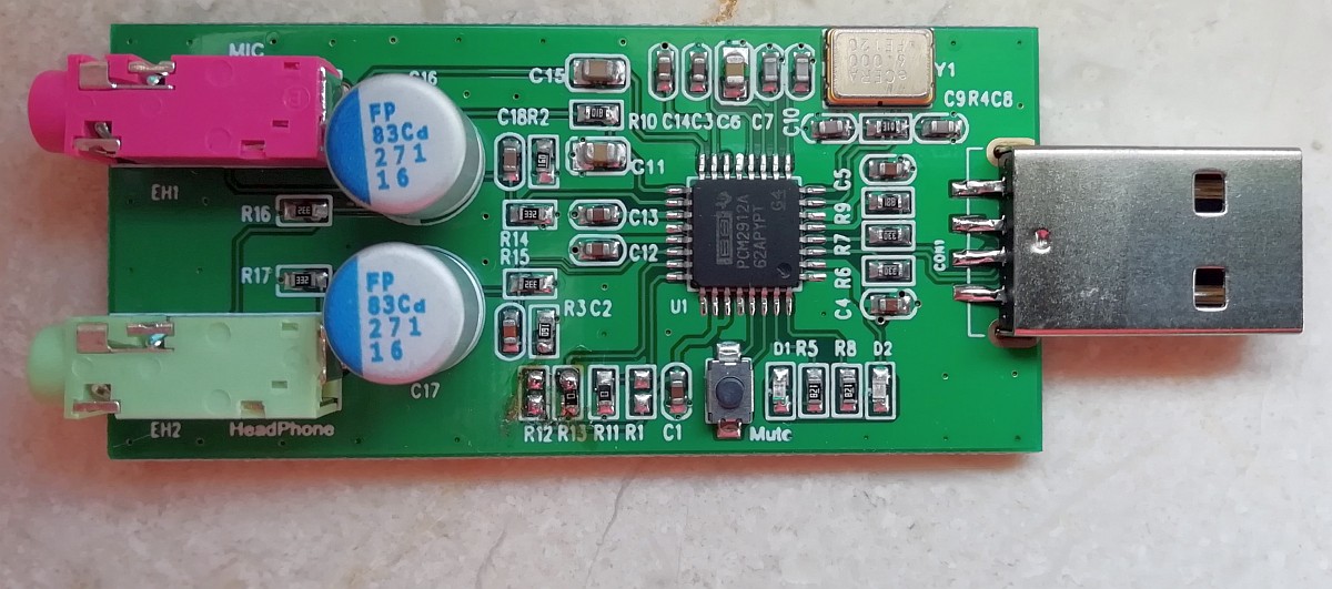
This is one of the good USB audio dongles. However, it was too sensitive, as the 20dB amplifier is enabled by default.
You can change that by moving the zero ohm resistor from position R12 to position R13 (has already been done here).
The sample rate is also adjustable at 22050 samples/sec. That significantly reduces the "CPU usage"!
Behringer's audio devices are also excellent!
And... how does he do it?
The sensitivity is fine at 20 meters and just good enough at 10 meters. The frequency stability is also sufficient. A little better would be desirable, but it's already better than many MEPT's! And the suppression of a sideband using the phase method also worked well at 10 meters!
The sideband suppression of the unwanted sideband is over 40dB and even over 50dB at the center frequency! There are no audible signals coming from that unwanted sideband. That was the case with the first simple direct conversion receiver without that unwanted sideband suppression.
No unwanted signals can be heard, which are often caused by these types of simple receivers due to overloading by strong broadcasting transmitters.
But not all USB audio dongles are of good quality. The cheapest ones have too much jitter, so the lines are not tight, but irregular.
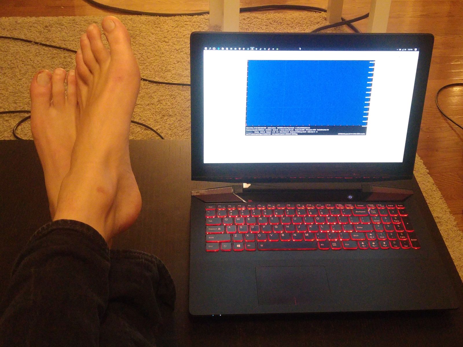
And now it is time to relax and wait for the results!
And... soon the first signals were received!
Unfortunately only one MEPT at 20 meters, but many WSPR stations.

And... a balloon!
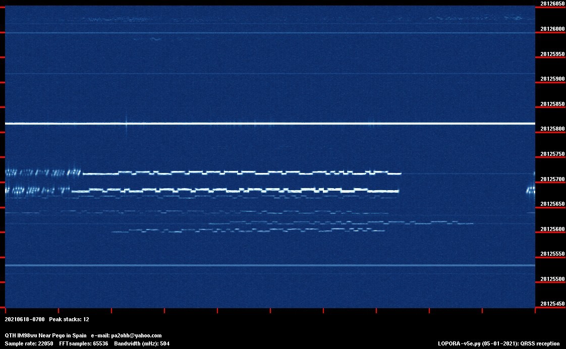
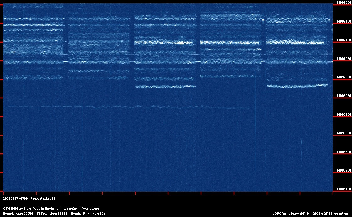
Luckily more stations at 10 meters. No less than 6 MEPTS during sporadic E.
And my calibration signal to test the frequency stability.
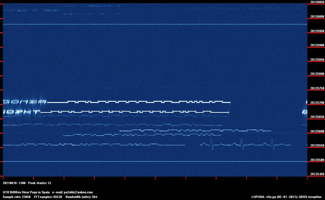
And another nice picture, with a heartbeat!
Index PA2OHH