QRSS RECEIVER FOR 80 METERS
(2020)
KLIK HIER VOOR DE NEDERLANDSE VERSIE
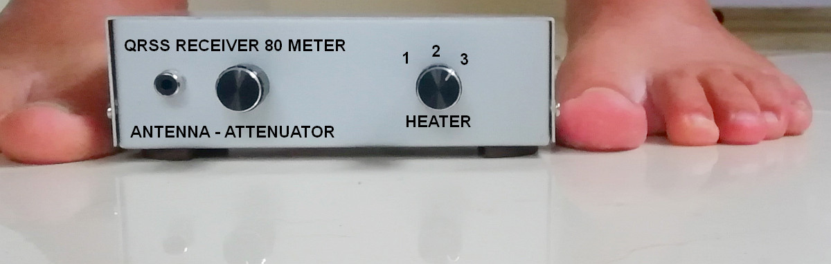
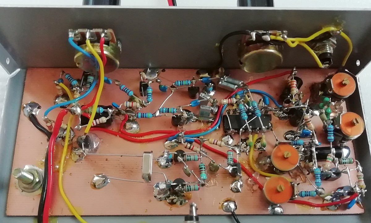
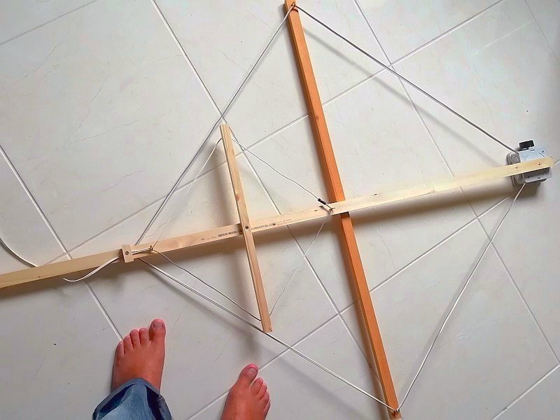
The QRSS receiver: On the left the antenna input with HF attenuator and on the right the temperature control for the crystal.
Those far too cold red toes on the horribly cold stone floor are a very important part of the simple circuit!
QRSS receiver for 80 meters
My motivator George emailed me, he was worried! Why did I only have 1 active QRSS receiver? Was I no longer motivated? Why didn't I walk barefoot in the shack anymore? I told it him many times. Only simple radio projects and very sober barefoot in the shack. Barefoot to avoid static electricity and because it's simple! And he loved that! I got excited and had a great idea! Back to work!
I wanted a simple, minimalist receiver, a very challenging simple and cheap design with alternative ideas and experiments! And also a stable frequency, that is certainly a challenge. The temperature in the shack varies between 8C and 31C! Is it possible to make such a receiver with simple means? With a very simple method for sideband suppression? Will I ever receive anything with it? Just a single signal is enough to make this project successful!
Get rid of those thick warm shoes and socks and that carpet! Barefoot on the ice cold tiled floor of my unheated shack in the middle of winter! But 8C degrees, that's way too cold for my bare feet and my poor toes are nowhere near able to withstand the terrible cold! But we don't want to wait until summer! Hopefully my poor toes will survive that horrible cold!
It always starts with some notes on a piece of paper!
Challenging simplicity and alternative ideas!
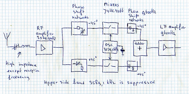
I had a bag with crystals of 3579,5 kHz. The QRSS band of 3569,9 kHz is 9600 Hz lower. It must therefore be a direct conversion receiver with a low-frequency output of 9600 Hz. Quite a high frequency that 9600 Hz, again a challenge! The unwanted sideband is suppressed by the phase method. The advantage of that high audio frequency is that the QRSS band of 200 Hz is only 1% around that 9600 Hz. So a very simple phase network of only one resistor and one capacitor can be used in the low-frequency path!
I wanted to use the 74HC4066 as a mixer, I had good experiences with that. There were still some of the brand Toshiba here. And we're going to use as many transistors as possible, not ICs, except for that 74HC4066 switch that's used as a mixer. I got very excited, it can really become a minimalistic, simple "Barefoot Technology" circuit! And that's what I want!
But wait, the local oscillator frequency is above the QRSS band. So first the Lopora QRSS software has to be modified to receive the low sideband. What a great, challenging QRSS hobby! After a few days, the Lopora software was modified, some other modifications were also needed.
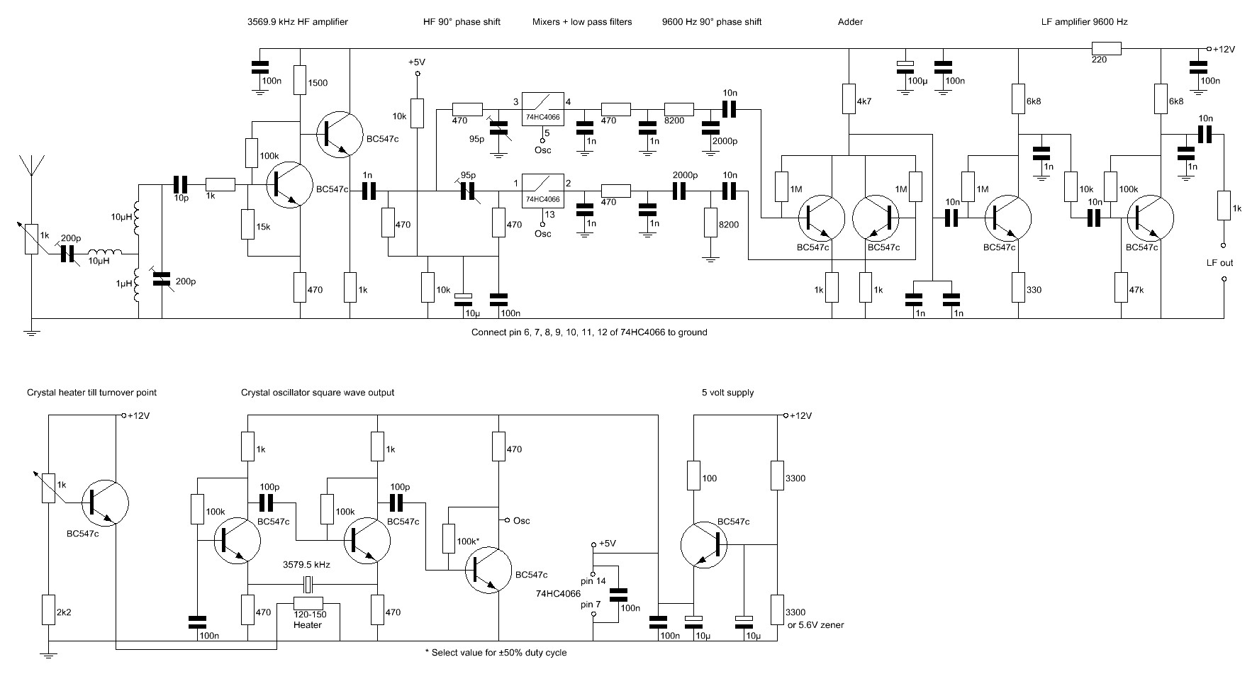
Schematic, almost all transistors! But it needs some explanation to understand everything!
HF amplifier
At the input is the HF attenuator, a 1k ohm potentiometer, with which the sensitivity of the receiver can be optimally adjusted and overload by strong signals can be avoided.
But why is there a series resonance circuit after the attenuator? Another interesting alternative experiment! It is tuned to the receive frequency of 3569,9 kHz and has a low impedance for that frequency only. It has a high impedance for other frequencies. And so you can connect multiple receivers for different frequencies in parallel with the antenna without attenuating each other's signals!
After this series circuit you will see the tuned circuit consisting of the coils of 1uH, 10uH and trimmer of 200pF. This selective circuit only allows a small band around 3569,9 kHz to pass through and attenuates the unwanted signals at other frequencies. You will not easily find a 200pF trimmer. But the value is composed of a parallel connection of a capacitor and a trimmer of a smaller value. For example, a capacitor of 180pF and a trimmer of 40pF. Or a capacitor of 150pF and a trimmer of 70pF.
Due to the high emitter resistance of 470 ohms, the first transistor has a high input impedance. So it will not dampen the tuned circuit. The capacitor with a small value of 10pF and resistor of 1k ohm protects the transistor somewhat against high voltage peaks and the resistor also prevents oscillation of the HF amplifier. The second transistor has a low-impedance output, which is necessary to drive the phase networks. And both transistors and the tuned selective circuit also amplify the signal.
High-frequency phase networks
After the HF amplifier, the signal is split into two signal paths. A 90 degrees phase difference must be realized with the aid of phase networks. The 95pF trimmers and 470 ohm resistors do this. With the trimmers you can optimally adjust the phase so that the suppression of the unwanted side band is maximized. One phase network is at -45 degrees and the other at +45 degrees, the difference is then 90 degrees. And does one signal need more signal and the other less? Then you adjust one trimmer to -50 degrees and the other to +40 degrees. So the trimmers not only adjust the optimal phase, but also the optimal amplitude!
And if the low frequency phase networks do not differ exactly 90 degrees, you can correct this with the trimmers. Then the phase difference in the high-frequency phase networks is a little less or more than 90 degrees. You will not notice that the reception sensitivity decreases slightly, it is probably not even measurable!
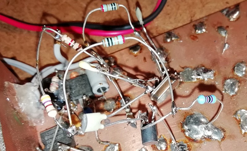
Real simple "Barefoot Technology"! The 74HC4066 mixer has just been mounted.
Everything is soldered to a printed circuit board and glued with a piece of glue of a glue stick (see top left).
Cut a piece of the glue stick and melt it with the soldering iron. Then clean it up!
Mixers
My QRP sets usually have a 74HC4066 as a receiver mixer. A simple, inexpensive solution that works fine, no audio detection of strong broadcast stations and excellent sensitivity. So it makes sense to use it here, I still have some! But you can also use a better, more modern FST3253 chip.
The mixers are simple semiconductor switches that are switched by the crystal oscillator of 3579,5 kHz. The IC 74HC4066 contains four of those switches, we only use two. A disadvantage is that HF signals and audio frequent signals are also passed from the input to the output. For example noise on audio frequencies from the HF amplifier. But the high-pass filter immediately after the HF amplifier consisting of a capacitor of 1000 pF and a resistor of 470 ohm only conducts HF signals and blocks these audio frequent signals.
The two-resistor voltage divider of 10k sets the mixer input to half voltage, which is 2.5 volts.
After the mixers you will see low-pass filters, each consisting of two capacitors of 1 nF and a resistor of 470 ohms. This filter only conducts low-frequency signals and blocks HF signals from the HF amplifier. This prevents detection of strong AM broadcast stations in the audio amplifier.
Low-frequency phase networks and the adder
After the low-pass filters, the two low-frequency phase networks can be found. These are capacitors of 2000pF and resistors of 8200 ohms. The frequency band used ranges from 9500 Hz to 9700 Hz. This is a very small deviation from the central frequency of 9600 Hz. And that is why we can use these simple networks consisting of only one capacitor and one resistor. One phase network shifts the phase by -45 degrees and the other by +45 degrees, the difference is then 90 degrees. And it does not have to be very accurate, it is not necessary to use very accurate components. If the difference is not exactly 90 degrees, no problem! You can correct this with the trimmers in the high frequency phase networks. You do not even notice that the reception sensitivity decreases slightly!
And it works! The suppression of the unwanted side band (3589,1 kHz) is more than 45dB and even more than 55dB at the central frequency!
The signals from both networks must be added. This is done in the circuit with two transistors and a common 4700 ohm collector resistor. The 1k ohm emitter resistors convert the input voltage into a current and both currents are added into the 4700 ohm resistor and converted back into a voltage. You do not need to use "paired" transistors with identical gain. The circuit also amplifies a bit: 4700 ohms / 1000 ohms or 4.7x.
Low-frequency amplifier
And then there are two transistors, the low-frequency amplifier. The first transistor has an emitter resistor of 330 ohms and a collector resistor of 6800 ohms. Due to the 330 ohm emitter resistor, this stage has a high input impedance and a decent negative feedback, so that practically no distortion occurs. The gain is approximately 6800 ohms / 330 ohms = 20x. Not quite true, the gain is only 12x, because the last stage loads the 6800 ohm resistor with 10k ohms.
The last stage also has much negative feedback. At the base is a 10k ohm resistor and between the collector and base a 100k ohm resistor. The gain is 100k / 10k = 10x. The 47k ohm resistor ensures the correct DC setting.
The 1 nF capacitors attenuate the high frequencies. And the 1k resistor at the output ensures that the output stage is at least loaded with that 1k impedance and is also a protection if you connect something crazy to the output.
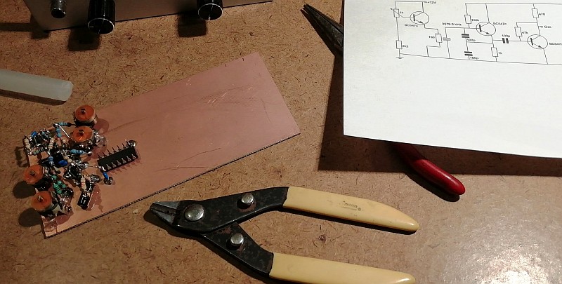
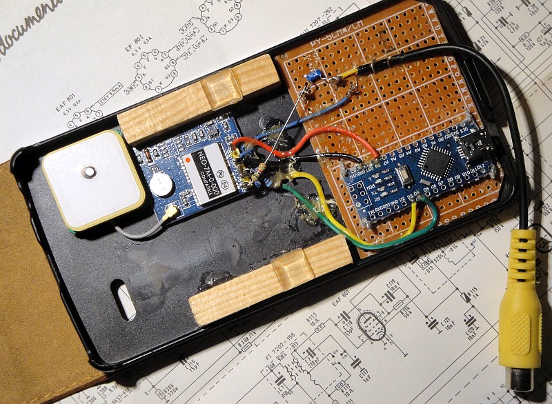
Test circuit of the crystal oscillator.
Crystal oscillator
And then another very important part, the crystal oscillator that controls the mixer. First I made a test circuit of the crystal oscillator. The original oscillator design was based on a Clapp oscillator. But the oscillator circuit used here is much more universal and operates over a very wide frequency range without the need to adjust capacitor values. Two transistors form the oscillator and it is followed by an extra stage that turns it into a square wave. You can change the 100k resistance of this last stage if the duty cycle is not 50%. You can measure this by measuring the average voltage on the collector, this must be half the supply voltage of the oscillator, so 2.5 volts.
The frequency of the oscillator does not have to be exactly 3579,5 kHz. That of my receiver is 3579,077 kHz or 423 Hz lower. The center of the band is at the audio frequency of 9177 Hz instead of 9600 Hz, but that is not a problem.
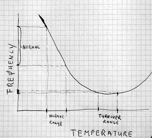
When we heat the crystal to the relatively flat turnover point, the frequency drift is much less!
We can easily heat this with a resistor, a real "Barefoot Technology" solution!
We need a very stable oscillator, how do we solve that?
The oscillator has to be very stable for QRSS reception. A drift of less than 1 Hz per hour is desirable. And also an absolute accuracy of 5 Hz. An ordinary crystal oscillator is not stable enough, there is too much frequency drift due to temperature variations. But when we heat the crystal to the relatively flat turnover point, the frequency drift is much less! We heat this with a resistor, again a very simple "Barefoot Technology" solution! We can control the current through the heater resistor with the 1k potentiometer.
Position 3: Far too cold red-purple toes!
Help! My poor toes can't stand this cold at all!
Thick warm winter clothes, because it is only 8C in the unheated shack and then barefoot on the ice cold tiled floor, that is way too cold for my bare feet!
I look at my bare feet on that far too cold floor! My terribly cold toes are nowhere near able to withstand the terrible cold and have scary red-purple colors due to the cold.
Awesome! I suddenly see a very alternative option to set the heater temperature and make a scale at the 1k potentiometer:
Potentiometer scale:
- 1: Warm toes!
- 2: Cold red toes!
- 3: Far too cold red-purple toes!
My toes are the cheapest and simplest temperature sensors for setting the temperature control! But then I have to walk barefoot on the far too cold stone floor all winter long! Hopefully my poor toes will survive that...
The "heater" resistor is soldered and glued directly to the crystal housing,
so that as much heat as possible is transferred to the crystal. Keep the wires of
the resistor long so that no heat escapes by conduction through the wires.
Heater resistor
The "heater" resistor is soldered and glued directly to the crystal housing, so that as much heat as possible is transferred to the crystal. Keep the wires of the resistor long so that no heat escapes by conduction through the wires. It works and is a very interesting experiment, but the crystal gets very hot and that also costs a lot of energy. The next QRSS receiver for 40 meters will therefore have a temperature control with an NTC resistor. Another new challenge!
Real simple "Barefoot Technology"!
This is the result! A very simple receiver with
all standard components. And it works great!
Power supply
The 220 ohm resistor, capacitors and 100nF capacitors are decoupling capacitors for the power supply to suppress interference signals. When the construction of the receiver was finished, it turned out that the 220 ohm resistor was 10 times larger, 2200 ohm. During the move, resistors have fallen into the adjacent box... Solved by connecting a 270 ohm resistor in parallel to it!
And then there is a 5 volt supply with a simple transistor. This is the supply voltage for the 74HC4066 and the oscillator. I did not have a suitable zener diode. But on the base is 6 volts, so on the emitter approximately 5 volts. The 100 ohm resistor in the collector is a current limiter, useful when you accidentally make a short circuit...
For the adjustment, the simple GPS frequency standard is used.
Adjustment
For the adjustment, the GPS frequency standard is used. The description can be found on this website. You can set the frequency to any value between 1 Hz and 10 MHz, even a few MHz higher with reduced quality. The low-frequency output is connected to the audio input of the PC and an audio spectrum analyzer program (there are many) is started on that PC. The GPS frequency standard is connected to the antenna input via a high-resistance resistor or a "pick-up" wire. Set the frequency of the GPS frequency standard to the QRSS frequency of 3569,9 kHz. Adjust the input circuit trimmers to maximum. You can vary the level of the test signal with the 1k attenuator potentiometer.
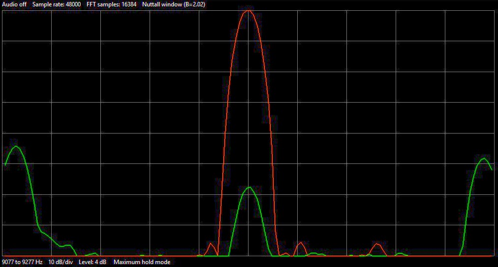
Adjustment of the suppressed sideband. The orange curve is the desired signal at 3569.9kHz.
The suppression of the unwanted side band (3589,1 kHz) is more than 45dB
and even more than 55dB in the middle of the band.
Sideband suppression
Now comes the difficult part, adjusting the sideband suppression, that will take quite some time.
Set the frequency of the GPS frequency to the QRSS frequency of 3569,9 kHz and adjust the signal with the 1k attenuator so that the signal is at the top of the spectrum display. Read the audio frequency. With my receiver that is 9177 Hz. Then set the frequency of the GPS frequency to the unwanted side band, which is 3569,5 kHz + 2x the read audio frequency. So for me 3569,9 kHz + 2 x 9177 = 3588,254 kHz. Now you will see a weaker signal in exactly the same place in the spectrum. Now adjust the two trimmers of the high-frequency phase network so that this signal is minimal. Always turn one trimmer slightly, then adjust the second to minimum signal and repeat it to find the most optimal positions.
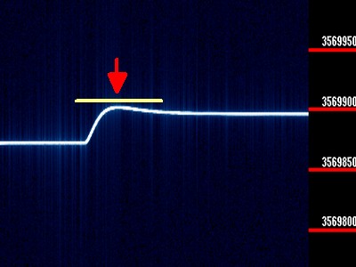
When you set the temperature control from the minimum to the maximum position, you will see
the turnover point under the arrow. Set the potentiometer at this turnover point.
How do you adjust the temperature of the crystal?
Set the frequency of the GPS frequency standard to the QRSS frequency of 3569,9 kHz and adjust the signal with the 1k attenuator so that the signal is in the spectrum display.
When you increase the temperature by slowly turning the control knob, you will see that the frequency first rises and then falls above a certain temperature. Set the potentiometer at this turnover point.
Real simple "Barefoot Technology"! A simple loop antenna for the first experiments!
All winter barefoot on the ice cold floor was quite a challenge, my toes barely survived that!
And... how does it work??
The sensitivity is excellent. When connected to a loop antenna, you can hear that the noise decrease enormously when you turn the HF attenuator back. The frequency stability is also excellent. There are no unwanted signals that are often caused by overdriving by strong broadcasting stations with these types of simple receivers.
And the side band suppression of the unwanted side band (3588,3 kHz) is over 45dB and even over 55dB at the center frequency! There are no audible signals from that unwanted sideband. That was the case with my first simple direct conversion receiver without that unwanted side band suppression.
Now we have to wait and see if we receive QRSS signals and there will certainly be experimented with antennas! Due to the high audio frequencies of 9600 Hz you must use a good quality USB audio dongle, not all cheap ones are usable. I am using a Behringer type UFO202.
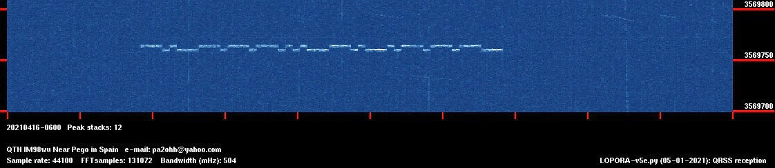
I can use the NanoVNA to generate a QRSS test signal, so I will receive at least 1 QRSS signal!
The first QRSS signal! Made with the NanoVNA!
Now we have to do many experiments with antennas!
Exciting!
A very strange, alternative receiver with a high audio frequency output frequency. And custom made software and that strange temperature compensation with my toes as a temperature sensor! Horribly cold red-purple toes that have to suffer terribly on the ice cold floor! It would have been much easier for me to buy an affordable commercial radio... But that's much less challenging! The very alternative temperature compensation works perfectly, but is very challenging cold for my toes! George told me, when you don't see that ice-cold tile floor as a problem, but as a challenge, it becomes a completely different experience! You have to see problems as challenges! That's why this QRSS receiver project was so much fun!
But beautiful signals, the 80 meter QRSS receiver is a great success, see the wonderful results below! I want to make more QRSS receivers, 40, 20 and 10 meters! And I promise my motivator to walk barefoot on that ice cold floor until something really bad happens to my toes. He finds that a challenging and very exciting experiment! And why not, when I lose a toe due to the cold, I still have 9 left! According to George, that is the right mentality I should have!
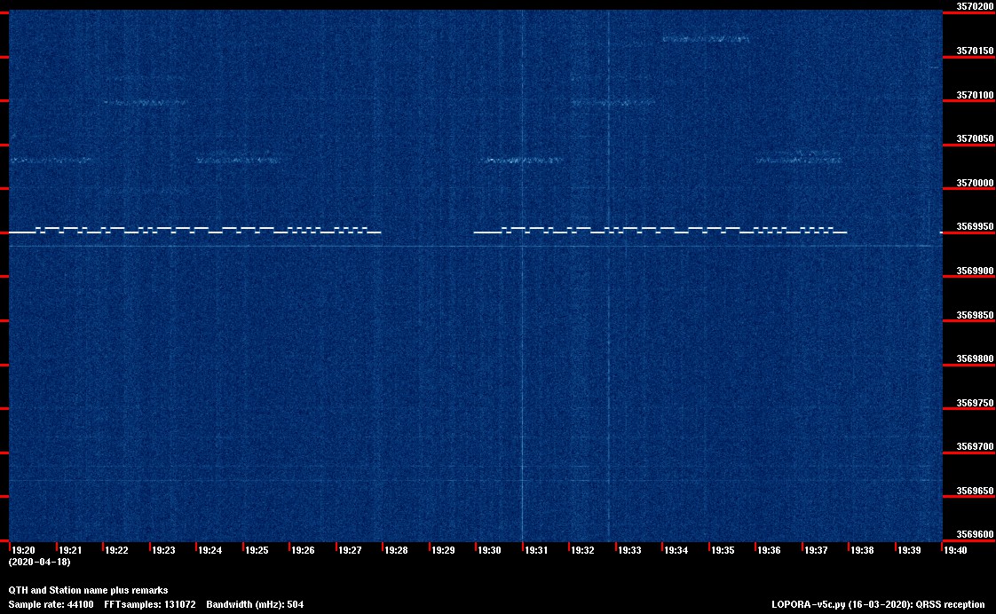
And... just after a few days the first signals were received!
G0FTD en VE1VDM! So this exciting project is already a success!
A very good signal from Vernon VE1VDM
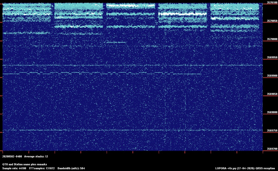
A very good signal from Andy G0FTD
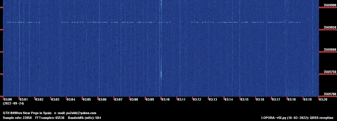
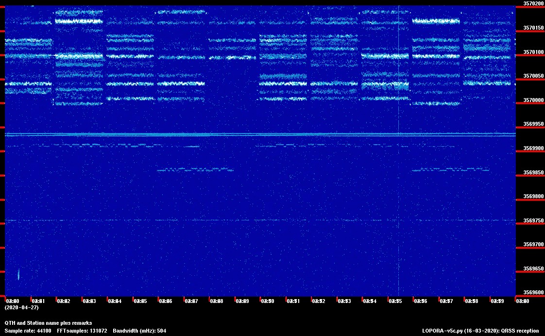
Joze S52AB
Larry N8NJ

Robert M6GLD
Excellent signals from Michael G6GN, Andy M0RON and Radovan OK1FCX (FSK3!)
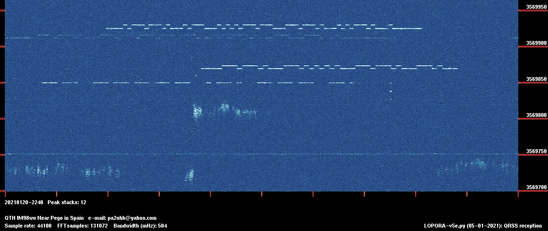
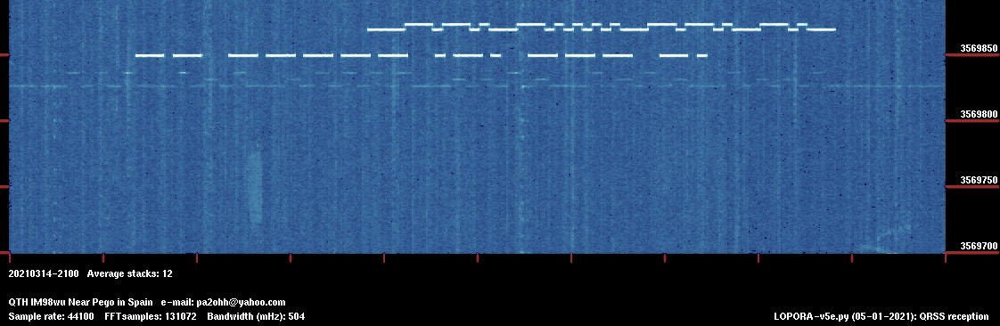
Four MEPTs! Martijn PA3GFE, G0FTD, G6GN, M0RON
QRSS Plus Automatically-Updating Active QRSS Grabber List by Scott Harden
Index PA2OHH