QRSS-LOOP ANTENNA CHALLENGE
(2020)
KLIK HIER VOOR DE NEDERLANDSE VERSIE

According to George, I can receive QRSS signals with such a small loop antenna!
QRSS loop antenna challenge!
Reception of QRSS signals with a small loop antenna, is that possible? Less instead of More, that is what this antenna experiment certainly is! According to George I can replace dipoles from 15 to 20 meters long with a very small antenna of only 1 meter, a loop antenna! An antenna that is 15 to 20 times smaller than the dipoles! According to George, I had to be able to receive weak QRSS signals with that! But it seemed to me absolutely impossible that you can receive something with such a small antenna!

And it should be foldable so that it can be easily stored!
How do you make such a loop antenna?
How do you make such a loop antenna? I did look at the internet for a few evenings. A frame made of wood and ordinary wire, not a copper tube because that is too difficult. For a transmitting antenna you want maximum efficiency and you have to use copper tube. But that is not so important for a receiving antenna, the receiver has enough gain to compensate the the lower efficiency. And it should be foldable so that it can be easily stored. And it must have a coupling loop, not a tap. Then the coupling loop is isolated from the tuned antenna loop, which is always better.
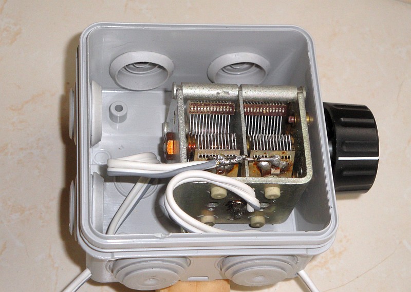
Why is the antenna so insensitive? It cannot be the tuning capacitor,
that is a good quality air capacitor!
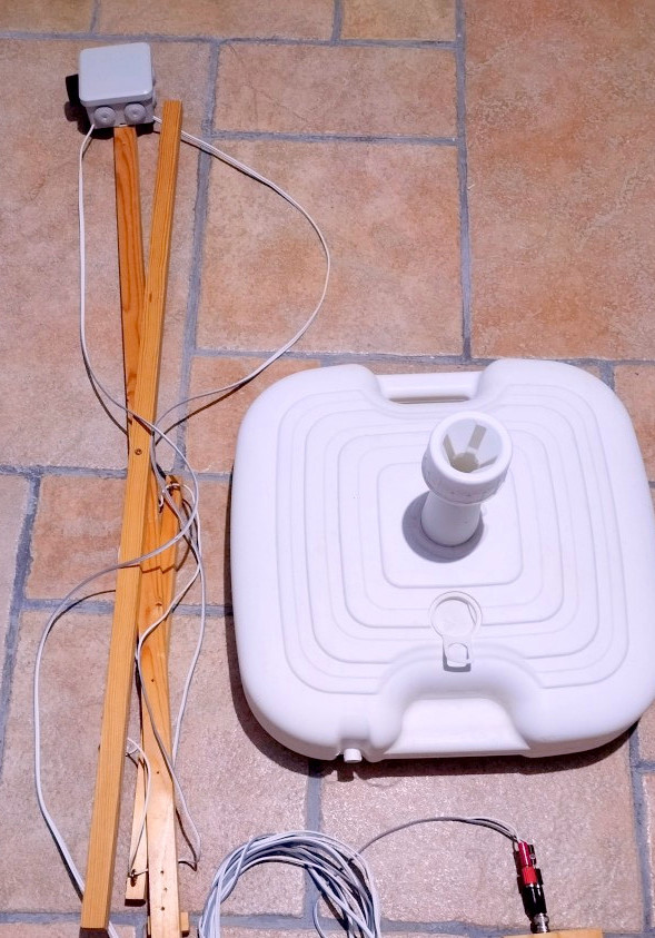
The construction
The tuning capacitor is a good quality air capacitor. Both sections of about 450-500 pF are connected in parallel, so that the final value is about 900-1000 pF. The plate spacing is not enough to transmit with it. But the loop antenna is not intended for that. Then you have to use real copper pipes instead of wire to keep the efficiency high. The large loop is made of twin wire, connected in parallel. Two wires in parallel gives a higher efficiency and I have just enough wire for that. The signal line is not a coax, but also identical twin wire. The coupling loop is a single wire. The twin wire signal line is spliced at the end and the ends are soldered together. That's the coupling loop. A frame was made of wood and the vertical stick fits exactly in a holder for a parasol. This makes it easy to set up and rotate. But no, the result was really bad, it was a very insensitive loop antenna... But I didn't expect anything else! I was right, George was wrong!!!

Left the NanoVNA that I could use to measure the SWR of the loop antenna.
On the right the GPS standard to calibrate the frequencies of QRSS receivers.
Coupling loop too small!
What could be the cause of the poor sensitivity? I had read it clearly, the diameter of the coupling loop must be 20% of that of the large tuned loop. And it is not the tuning capacitor, it is of excellent quality with air as a dielectric! Maybe that twin wire? No, that was what the dipole and the signal line to the dipole were made of, it couldn't be that!
In the meantime I had bought a NanoVNA with which I could measure the SWR of the loop antenna. And... that SWR was very bad !!! Was it the diameter of the coupling loop? It had to be 20%. But I had also read somewhere that not the diameter, but the surface should be 20%! In that case the diameter should be 45%, in my case 45cm! Because the tuned large loop has a diameter of 1 meter!
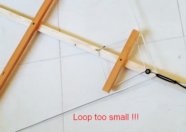
Coupling loop too small!
Success at last!
Adjusting the diameter was quickly done on that wooden frame, just replacing the horizontal bar with a longer one. And... a good SWR and a good sensitivity!!! The loop antenna was now working properly! The range is from 3.3 MHz to 16.1 MHz. The SWR is a bit worse at 3.3 MHz, but the antenna is still very useful for the reception of signals at 80 meters! I could tell George that the loop antenna was working fine now!
But first some pictures of the SWR, made with the NanoVNA. The loop antenna is very narrow and tuning is quite difficult. So you have to mount a big knob on the tuning capacitor! And even better is an extra reduction gear.
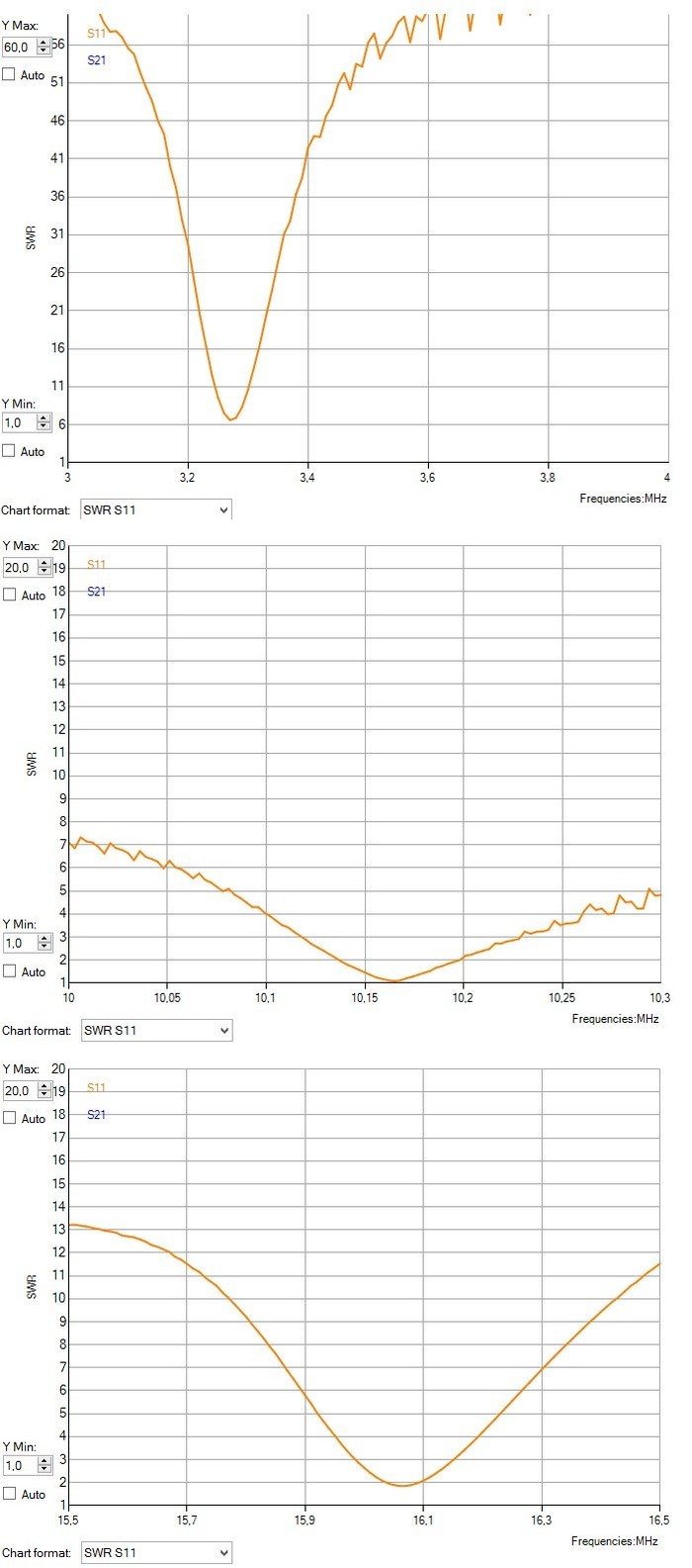
The SWR measurements at the lowest frequency, at 10.15 MHz and at the highest frequency
Usable from 3.3 MHz to 16 MHz
The SWR measurements were good, the antenna can even be used on all amateur bands from 80 meters up to 20 meters! But the results were somewhat disappointing at 30 meters, the indoor dipole just below the roof was slightly better. But it could be made better! Sometimes/often you have to be lucky! By coincidence I found out that it worked better with a symmetrical antenna amplifier! This was not due to the extra gain, because I had to attenuate the signal after the amplifier. It was because of the symmetrical input! Noise interference from the computer was conducted to the antenna via the signal line.

The HF isolation transformer for the suppression of local interferences.
This consists of 2x8 bifilar windings, two twisted wires on an FT37-43 core.
HF isolation transformer for the suppressing of local disturbances
The solution is an HF isolation transformer! Then the coupling loop is symmetrically loaded and insensitive to electric fields! And there is no conductive interference via the signal line to the antenna! An HF isolation transformer was made. This consists of 2x8 bifilar windings, two twisted wires on an FT37-43 core. The loss is less than 1 dB, the isolation between the windings more than 20 dB at the lower frequencies. You can measure all that with that simple NanoVNA! And the noise interference is now less as you can see further on in the picture. This test was performed at 80 meters, but the results are comparable on other bands.
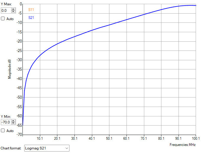
The isolation between the two windings of the HF isolation transformer measured with the NanoVNA

The HF isolation transformer tested.
The lighter band in the middle is without the HF isolation transformer, so more noise interference. At the left and right of it
you can see the weak vertical lines of a thunderstorm. You don't see that in the middle without the HF isolation transformer!
Some test results
The loop antenna was doing great now! Maybe even better than the dipole! "Less instead of More", it is possible! I did not expect that the loop antenna would work so well. The signal is slightly weaker than that of the dipole, but that is the background noise too. The signal to noise ratio is just as good or maybe even better. Slightly less signal is not bad, the receiver has more than enough gain to compensate that! Below a few tests at 30 meters to compare this small 1 meter loop antenna with the much larger dipole antenna!

Left of center is the reception with the dipole antenna. Right of center the reception with the loop antenna.
Is the reception on the right with the loop antenna really better? Definitely not worse !!!
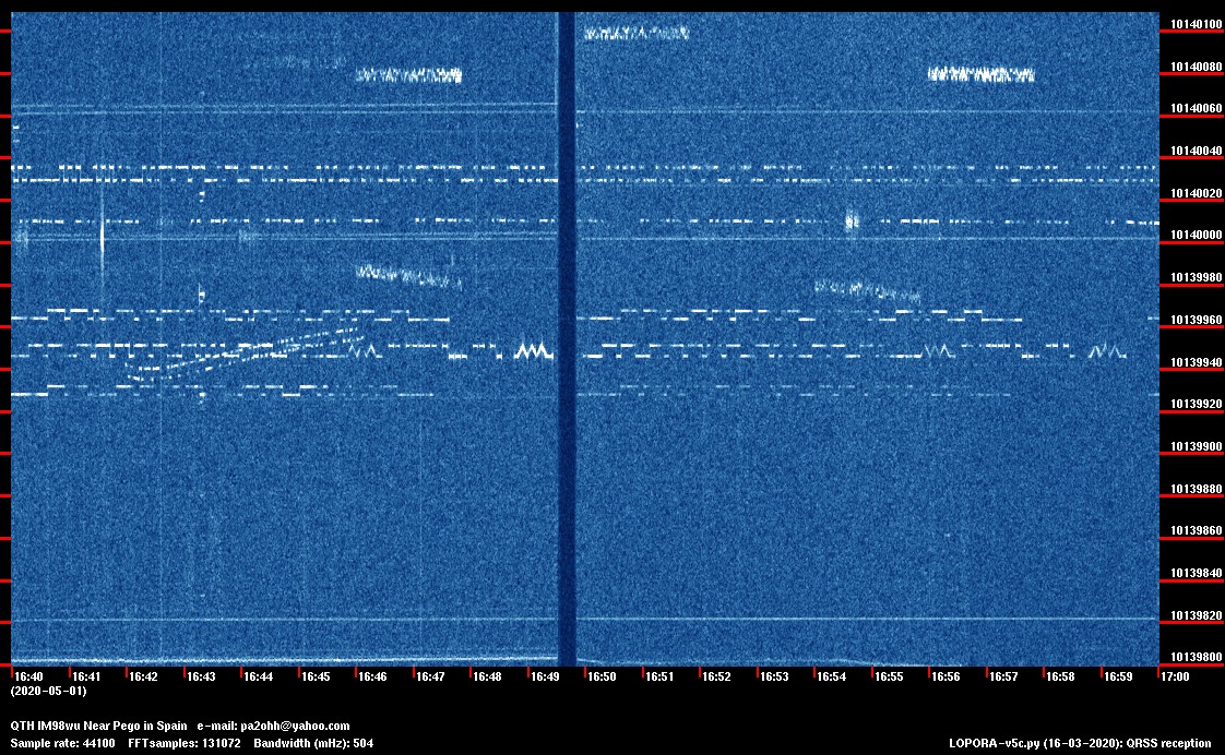
Left of center is the reception with the loop antenna. Right of center the reception with the dipole antenna.
Is the reception on the left with the loop antenna really better? Definitely not worse !!!
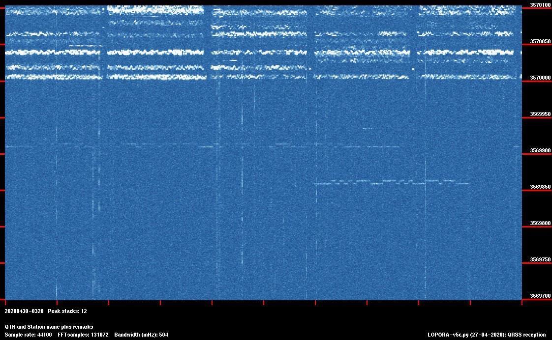
And here the reception at 80 meters, almost the lowest frequency of the loop antenna.
VE1VDM (VDM) is clearly visible and above that a very weak signal from G0FTD.
QRSS GRABBER WITH THE LOOP ANTENNA AND A NEW RTL.SDR VERSION 4 DONGLE
And then there came a new version 4 RTL.SDR dongle! This new version 4 of the famous RTL-SDR blog dongle uses a built in upconverter instead of using a direct sampling circuit. So the reception on HF bands is much better than the previous version 3! The loop antenna adds also input selectivity so that the dongle only has to process a small part of the spectrum! A cheap RTL.SDR dongle and a small loop antenna but... Excellent results on all frequencies within the tuning range of the loop antenna!
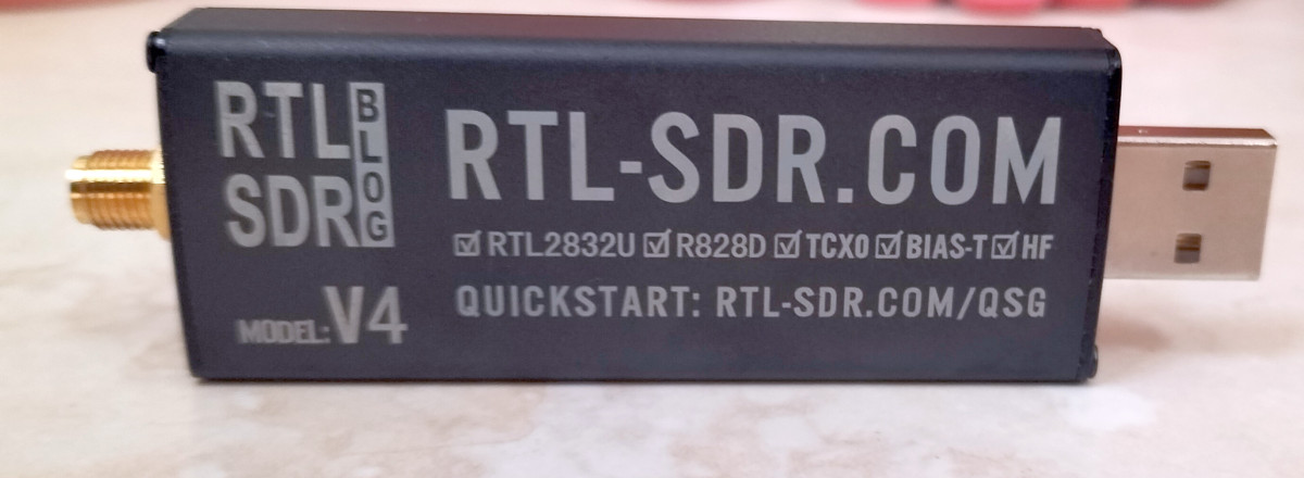
The new version 4 of the famous RTL-SDR dongle!
It can be easily stored when not in use!
Index PA2OHH