THE MISTAKE IN MY FIRST TUBE RADIO
(2019)
KLIK HIER VOOR DE NEDERLANDSE VERSIE

This was my first self-built radio. The regeneration did not work properly.
But when you are 11 years old you cannot always find the fault!
My first home-built radio
I was 11 years old and had my own place to play in the attic. Playing with lego and meccano I loved that! And with batteries and lights. And an old electric bell. And I got a kit with which you could build a radio with transistors. I found those radio parts very interesting! I wanted to make my own radio! I wanted to learn how to solder, I got an old soldering iron! I wanted to make a radio with a tube! A regenerative radio with a tube is much better than the kit radio with transistors! And a tube radio can be connected to an antenna, the transistor radio couldn't, it had a ferrite antenna!
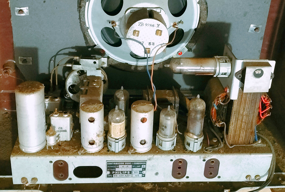
As a child I saw this! And I wanted to learn what you
can do with those interesting parts! Learn to solder first!
Difficult project for a child of 11 years old
With great effort and some help I managed to make the radio. It was a great challenge. Making such a simple radio is not easy for a child of 11 years old. My first home built radio! But it was disappointing. The regeneration did not work smoothly. Or it did not oscillate or oscillated very strongly, I could not set it to the edge of generation. And with those filaments it was a huge battery eater. I was only 11 years old and did not know what to do, I had too little knowledge and experience... Then it happened, I accidentally connected the filament to the 12 volt battery and the tube was damaged... The radio was "history"... Because a new tube was too expensive, the radio was not working properly and I wanted to use the 402 coil for a new transistor radio. I no longer wanted tubes, they were worse than transistors!

The 3B4 (DL98) that I got
I had the opportunity to rebuild and try this radio
Alex had said it a few times in my student days. I had to try again to build that receiver and find out why the regeneration didn't work properly. But no, there was always a reason not to do that. Until last year! I got a tube, a 3B4 and a 402 coil, so it was possible to rebuild the radio and find out what the problem might have been! The original version had a crystal phone, but I wanted to try this version for high-impedance headphones. There are no more crystal phones. You can easily turn a low-ohmic headphone into a high-ohmic by means of a transformer. The 3B4 (DL98) is a slightly different version than the original DL92. But a tube is a tube, so...

First find all the parts together and buy a wooden box
I never have known why the regeneration didn't work properly. I often thought that I had the 1.5 volt battery for the glow voltage connected the wrong way, with reversed polarity. Then the grid has a positive bias and then there is too much grid current. Or is it something with the regeneration? And that output circuit does not seem right to me now. Surely there must be a coil between the transformer and anode to block the high-frequency signal! And that capacitor should not be connected across the transformer, but to ground! As a child of 11 years old I did not know that. I built everything exactly as it was on the drawings.
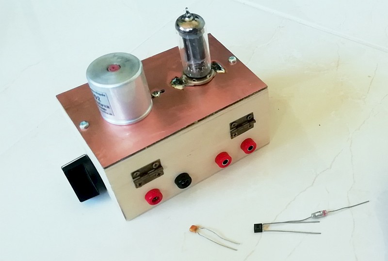
Almost done, just a few more parts have to be soldered.
A real simple "Barefoot Technology" radio!
The construction
I bought a wooden box and collected the parts. That happened quickly. There are very few parts in such a simple "Barefoot Technology" radio! Sawing a printed circuit board to mount the tube and coil, drilling and filing holes in the wooden box, it was two evenings of work. And then another evening to install the parts and the wiring. Wonderfully relaxing! A little glue and the radio was ready! As an 11 year old child it was a very difficult, strenuous project, now it was a very simple, relaxing project!
I have checked a few times if the filament is connected to the 1.5 volt battery and not to the 12 volt supply! No I didn't want to make that mistake again! But such a tube has two filaments. Why should I use them both? In this application there is very little current running and one filament should be sufficient! The battery lasts twice as long!

What is in the box? Very little!
Adjustments and result
The capacitor C4 was not connected to the plus, but to ground. Then the HF is decoupled to ground. Also, a capacitor of 0.1 uF was placed between the screen grid/+power supply and ground to disconnect it. A 1500 ohm resistor is fitted between the anode and the transformer/C4. That gives sufficient signal for the regeneration. Now the circuit is no longer dependent on the HF properties of the battery.
The receiver was connected to a few meters of antenna wire. The regeneration worked very smoothly. The sound is not very loud, it requires a longer antenna wire. And the tube clearly works better when both filaments are heated. But what a glow wire current! More than 300 mA! Then the batteries will be quickly sold out in the village... That is why I have connected each filament to the 12 volt supply voltage via a series resistance of 100 ohms / 2 watts. And if I set the voltage to 15 volts, the receiver also works a little better.
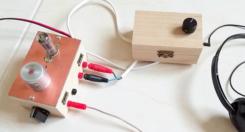
The receiver with the transformer to make high-impedance headphone from a low-impedance one,
see:
High impedance headphones
But what is the mistake I made as a child?
But what happened when I reversed the polarity of the filament battery? Then the regeneration does not work smoothly! Or it did not oscillate or very strongly, I could not set it to the edge of generation! So the mistake I made as a child has finally been found! I had reversed the polarity of the filament battery! Finally, after many years, that riddle has been solved!
Index PA2OHH