QrssPiG AND THE RTL.SDR AS QRSS GRABBER
2018
VOOR VERTALING IN HET NEDERLANDS, KLIK DE RECHTER MUISTOETS EN KIES "Vertalen in het Nederlands"
QrssPiG with an USB audio device was a success!
QrssPiG with the RTL.SDR dongle!
QrssPiG with an USB audio device was a success! But I also had an RTL.SDR dongle and it is possible to use such a dongle with QrssPig! The RTL.SDR dongle is a nice, cheap all band receiver with a very acceptable performance. However, the performance was not good enough to use it as a grabber. The reception was already much better with a selective antenna tuner. The antenna tuner does increase the input level to the receiver and also creates extra input selectivity. It was not too difficult to modify the RTL.SDR a little to make it usable as a QRSS grabber! And now I do have not only a 30 meter grabber, but also a 40 meter grabber. Both are running on the same Raspberry Pi! And it is simple to tune and use it for 20 meter or 80 meter! The RTL.SDR dongle as a grabber, that what seems impossible is possible if you do not give up too quickly!

The RTL.SDR is modified to use it as a QRSS grabber. On top a hole for tuning the bandpass filter.
Next to the Direct sample antenna input a hole for adjustment of the RF attenuator.
Ideas for improvements
The ideas for the RTL.SDR improvements were to add some extra gain, to add input selectivity and to add a variable RF attenuator. It should all fit in the original RTL.SDR housing. Normally, all the signals from 0 to 30 MHz will reach the 8 bit A/D converter. The selective band filter will reject most of these signals, only the signals around the reception frequency will pass. A crystal filter would be the best option but is too complex. So a single L/C filter is used. And an adjustable potentiometer as RF attenuator at the input. Set it so that the noise floor just increases when you connect the antenna for the optimal dynamic range.

Diagram.
Explanation
The potentiometer of 1k ohms is inserted between the antenna connector and the original low pass filter of the RTL.SDR dongle. It is the simple RF attenuator. The original 47 ohms resistor of the RTL.SDR dongle after the low pass filter is removed. After the low pass filter, a new selective filter is made, consisting of the inductors of 1 uH, 10 uH and a trimmer capacitor of 60 pF. With the trimmer, the band filter can be tuned to 7 MHz and 10 MHz. For 3,5 MHz, you have to solder a capacitor of 150 pF parallel to the trimmer. For 14 MHz, solder an inductor of 10 uH parallel to the trimmer, or replace the 10 uH and 1 uH inductors by 4,7 uH and 0,47 uH. But 14 MHz is very close to 50% of the sample frequency of 28,8 MHz (14,4 MHz), so do not expect too much from this frequency band.
After the band filter, there is a BF494 emitter follower as impedance match between the band filter and the RTL.SDR input. The BF494 has a deviating pin layout from a "standard" transistor! The 1k ohms resistor at the base is important, it avoids oscillations. Gain is obtained because of the up-transformation by the band filter. The antenna is connected at a tap of the band filter, to the 1 uH coil, the transistor at the top.
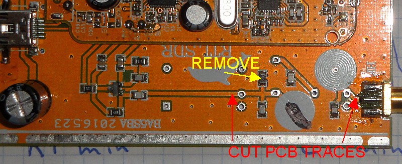
Remove the resistor of 47 ohms after the low pass filter and cut the two PCB traces.
Modification of the RTL.SDR dongle
Barefoot during this long, exciting project with QrssPiG! Barefoot on the horribly cold stone floor of my unheated radio lab to avoid any damage due to static electricity! A real "Barefoot technology" solution for the problems with electrostatic discharges! Minimalistic, simple and challenging! Great! Such a cold barefoot challenge gives you much energy!
Remove the resistor of 47 ohms after the low pass filter and cut the two PCB traces. Build the whole circuit on the PCB as you can see here below. Make two holes in the housing so that you can adjust the trimmer and the RF attenuator with a screwdriver.

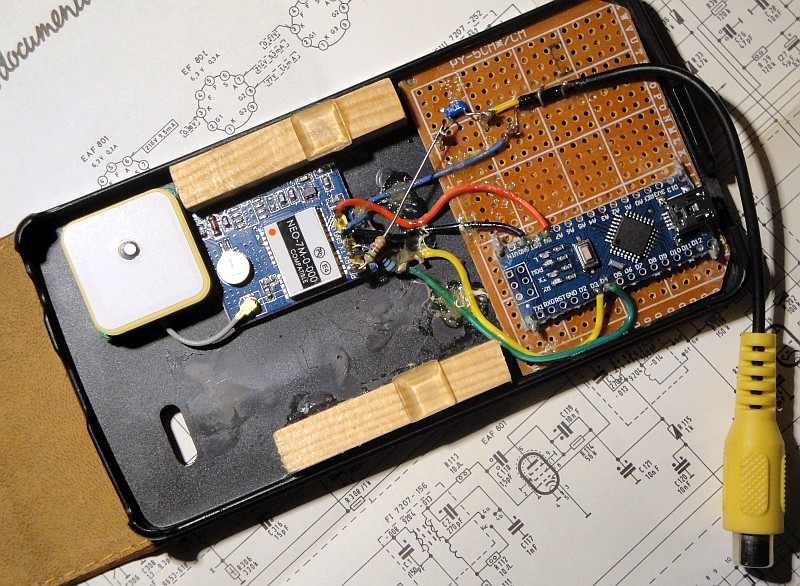
The modified RTL.SDR dongle.
Simple test equipment!
Test signals are required to compare the RTL.SDR receiver with my "standard receiver". A cheap GPS module with reference frequency output is used as RF generator for the test signals. When a weak signal is needed, tune the RF signal to an odd division of the test frequency (1/5, 1/7, 1/9, etc.). And the frequency is GPS controlled, so it can also be used to calibrate the frequency of the RTL.SDR receiver.
See: GPS frequency standard and RF generator for the details about this RF generator.
A cheap GPS module with reference frequency output is used as RF generator for the test signals.
Reduction of the frequency drift
If you want to buy a dongle, order the version 3. It has a TCXO, so almost no temperature drift. And it has one input for both HF and VF frequency ranges. But it is not possible to modify it so easily as the one I ordered.
The RTL.SDR dongle I bought had too much frequency drift in the range of 9C minimum to 30C maximum. I wanted a sample with a TCXO, but it was not available. How can we reduce the frequency drift of a normal crystal oscillator? With a simple "Barefoot technology" solution, only one resistor!!!
When the crystal of the oscillator is heated up to the flat turnover point, then around this point, the temperature drift will be much lower. I heated it up with a resistor glued onto the crystal. Keep the wires long, so that all the heat is transferred to the crystal and not via short wires to the PCB and other components. The RTL.SDR is placed upside down to have a maximum heat transfer to the crystal.
I tried a resistor of 100 ohms connected to the 5 volt supply of the RTL.SDR, as that was the value I needed for my first RTL.SDR dongle. But 100 ohms was not the right value for this RTL.SDR receiver. With a resistor of 47 ohm, the turnover point was close to 24C. Do not go too far above the turnover point, above that point the temperature drift increases more rapidly than below that point.
See: RTL.SDR frequency stabilizer, the most simple circuit for the details.
However, there is also a continuous aging process of the crystal. Every 1-2 months I have to change the PPM value to make a correction for that aging process, it has nothing to do with temperature drift...

Adjustment of the bandpass filter.
Adjustment of the bandpass filter.
Connect the RTL.SDR dongle to a PC with an SDR software program like HDSDR or SDRSharp (SDR#). You need a signal to tune the bandpass filter to the desired frequency. Tune the trimmer for a maximum signal on the spectrum screen. The already mentioned GPS module can be used as signal generator, you can also use it to calibrate the receiver. But it is also possible to use the Raspberry Pi as RF generator.
See: RF generator with the Raspberry Pi for the details.

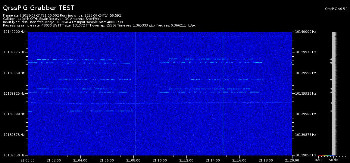
At the top the received QRSS signals with the reference receiver.
Below the received QRSS signals with the RTL.SDR dongle and QrssPiG.
Results
As you can see, the modified RTL.SDR dongle performs well when compared with the reference grabber receiver. However, a dongle such as this one is not the best choice for a grabber receiver, as it only has 8 bits A/D conversion. A sound-card has at least 16 bits and the receiver can be provided with a narrow audio band-filter so that only the desired audio frequency band is processed by the A/D converter of the soundcard instead of a whole part of the RF spectrum. But you do not need an extra power supply for the dongle, as the power is supplied via the USB cable from the Raspberry Pi. And the dongle has a small enclosure! I do use it as a 40-meter grabber. It is connected to the same Raspberry Pi as my 30 meter grabber receiver. So one Raspberry Pi 2B is used for two grabbers at the same time!
With the heating resistor, the frequency drift due to temperature change is acceptable. A version with TCXO was not available when I ordered my RTL.SDR dongle.
Of course, you could modify the circuit so that you have switches and a trimmer for each band and a switch to use the RTL.SDR dongle in its original state.
For frequencies higher than 24 MHz, you can use the second UV tuner input, which is unaffected by the modifications of the HF direct sampling input.
Installation of QrssPiG.
You can find QrssPig at: https://gitlab.com/hb9fxx/qrsspig where also an explanation is given about how to install it from repository for the distribution "stretch" and how to run QrssPiG.

YAML configuration file settings for HF direct sampling input.
Do not use tabs but only spaces for the indents!
QrssPiG YAML configuration file settings
The RTL2832U chip of the RTL.SDR dongle can sample from two ranges: 225.001 to 300.000 and 900.001 to 3.200.000. However, the upper range does not work with the Raspberry Pi, so pick any number that lies between 225.001 to 300.000. I chose 240.000, an integer division of 28.8 MHz. It is always better to take an integer division if possible.
Autostart of the grabbers with the Raspberry Pi
Autostart can be a little problematic in Terminal mode, because you have to set the command in the file "/etc/rc.local". This file is executed while Linux is booting up and before any users have logged in. And if there is an error in your program, it might be that the Raspberry Pi does not boot anymore! But normally, we do not use the Terminal mode, but the Desktop mode. So I did the Autostart in Desktop mode. The grabber starts now automatically after a power failure!
Open with the File Manager the /home/pi directory.
Open the directory /home/pi/.config (Activate in the File Manager: View: Show Hidden!)
Make a new directory (folder) "autostart" and make a desktop file in this directory /home/pi/.config/autostart/
The name of the Desktop file is "grabbers.desktop" and you can find the text in the screenshot here below.
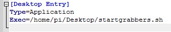
Desktop file with the name "grabbers.desktop", located in the directory /home/pi/.config/autostart/
Make the Desktopfile "grabbers.desktop" executable (click the file with the right mouse button, select "Properties" --> "Permissions" --> "Execute" and set it to "Anyone") and when the Raspberry Pi reboots, the grabber will start after the mentioned 2 minutes. Just wait, it looks as if nothing happens.
The scriptfile "startgrabbers.sh" is located on the Desktop. If necessary, you have to modify the Exec=.. so that it runs your scriptfile name.

The scriptfile "startgrabbers.sh" is located on the Desktop.
But it takes approximately 2 minutes to start the grabbers with this script file due to the following reasons:
My Raspberry Pi starts much faster than my Internet modem. As the modem was not rebooted, it could not get the right time via the time server and did start to run with a wrong time. So in the script file, there is a pause to give the Internet modem enough time to reboot. In the previous versions of the software, the NTP Network Time Protocol service had to be restarted, so that it can get the correct time from the Internet via the rebooted modem. But not anymore in the latest versions (NOOBs V2.8.2)
Index PA2OHH