IMPROVED 30 METER RECEIVER FOR
LOW POWER QRSS BEACONS AND PSK31
(2009)
KLIK HIER VOOR DE NEDERLANDSE VERSIE
Reception of very low QRSS beacon transmitters
It seems unbelievable. During my holidays in Spain, it was possible to receive a 10 milliwatt beacon transmitter located in The Netherlands at a distance of 1650 km!
There is a group enthusiastic radio amateurs that is doing experiments with very low powers. That is possible by using a very slow CW speed. QRS mean reduce your CW speed. With that extra S of QRSS they want to indicate that it is really a very low CW speed. A point lasts 3 or 10 seconds. Most of the activities take place in a band of only 100 Hz: 10140.0 to 10140.1 kHz in the 30 meters amateur band. The signals are so weak, that you cannot hear them. But you can see them on the monitor of the PC. The audio output of the receiver is connected to the sound card of the PC. With a special software program, you can make bandwidths of 0.3 Hz or even less and display the signals on the monitor.
From double side band to single side band reception! In the improved
receiver, the unwanted side band is suppressed with the phase method.
From double side band to single side band reception and from 10 milliwatt to 1 milliwatt
The experiment was successful with 10 milliwatt in the 30 meter amateurband. The new challenge was to try it with 1 milliwatt or a factor 10x or 10 dB lower. That is 1000x lower than the 1 watt of my small QRP transceiver!
A gain of 3 dB can be obtained when the direct conversion receiver is modified from a double side band receiver to a single side band receiver, as the noise of the unused side band is suppressed then. And 5 dB gain by setting the dotlength of the software program ARGO to 10 seconds instead of 3 seconds. In total, we would have 8 dB gain, or almost the 10 dB power reduction!
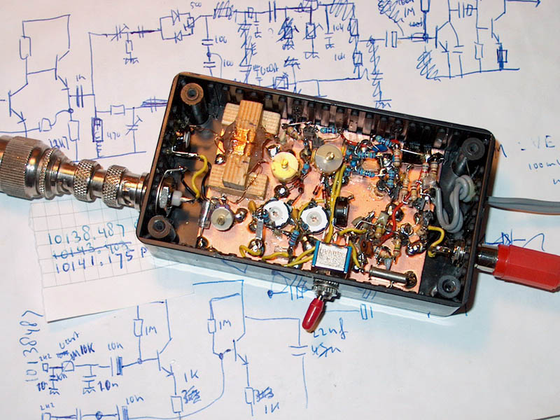
There was some space left in the plastic housing of the simple direct conversion receiver. Just enough to modify the simple receiver with the phase method to a single side band receiver.
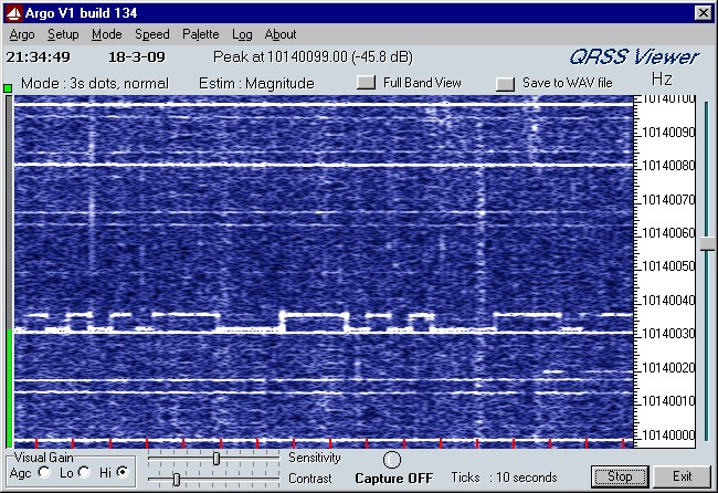
The beacon transmitter was also modified. The transmit times were extended and the power was reduced. During the low shift, the power is 1 milliwatt, during the high shift even lower, 0.1 milliwatt. Should it be possible to receive that 1 milliwatt and 0.1 milliwatt during holidays in Spain? Here below the result.
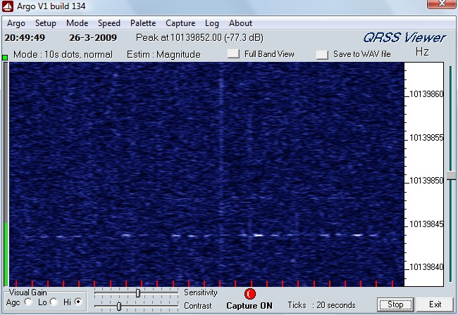
The beacon signal with a shift of 4.2 Hz, 10 s low shift with a power of 1 mW.
So the 1 mW beacon could be received at a distance of 1650 km!
Even a very weak trace is just visible of the 13 s high shift of 0.1 mW.
Of course, everything has to go well. The conditions have to be excellent, the interference in a dip, you need to have the luck that you are listening just on the right moment, the frequency drift of the transmitter and receiver have to be minimal. You can receive the weak signal only at those excellent moments. It is important that your receiver is tuned to the frequency of the transmitter with an accuracy of plus or minus 30 Hz, so that you are looking at the right frequency when the conditions are good.
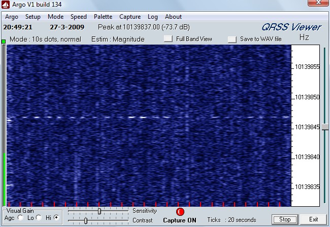
Here a registration during 8 minutes. Unfortunately there was much QRN that evening,
otherwise, the 4.2 Hz higher 0.1 mW signal perhaps had been clearly visible!
Modified receiver with side band suppression
It was quite simple to modify the simple direct conversion receiver with the phase method to a single side band receiver. Two mixers were required instead of one and simple phase networks in the RF part and LF part. As the frequency band of 10140.0 MHz to 10140.1 MHz is only 100 Hz wide, we can use two very simple LF phase networks consisting of one capacitor and one resistor. That is an advantage, because there is not so much space in the plastic housing of the receiver. And the receiver has to be supplied with batteries, these networks do not require any current. A wide band 90 degrees phase networks with op-amps in the audio part was not possible.
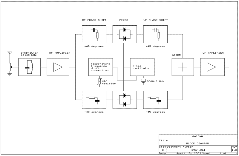
Block diagram. The phase networks do suppress 1 side band.
The Poljakov mixers do need a local oscillator signal of half the reception frequency.
Explanation of the schematic diagram
A part of this explanation is a copy of the explanation of the first version of the receiver.
We will start with the RF amplifier and RF phase networks. T1 is an ordinary LF transistor. The tuned circuit is adjusted by ear for maximum sensitivity. L2 is 20 windings on a wooden core of 8x8 mm with a tap at 2 windings to the base of T1. The antenna winding L1 of 2 windings is wound over the center of L2. The (adjustable) potentiometer P3 of 1k is the RF control. It is used to avoid overloading of the receiver in the evening by strong broadcast stations. You can use an adjustable potentiometer as it is not adjusted so often, only once or twice per day.
T1 is followed by an extra transistor T2 that transforms the high output impedance of T1 to a lower impedance. That is necessary to feed the phase network.
There are two 45 degrees phase networks between the RF stage and the mixers. They are adjusted by the trimmers. For that purpose, you do need a signal at the unwanted side band. Adjust the trimmers by ear to maximum suppression of this signal. You have to repeat it a few times, as the settings of each network do influence each other.

Circuit diagram
Mixer and LF phase networks
The mixer is a so called RA3AAE or Poljakov mixer. It works with a local oscillator signal of half the reception frequency. And that is the frequency of a cheap, easily obtainable crystal of 5068.8 kHz. The oscillator level is quite important and can be adjusted by ear with P2.
With a good adjustment by ear of P1a and P1b, the sensitivity for strong AM signals can be reduced considerably.
After the mixer and the RF decoupling networks consisting of resistors of 2200 ohm and capacitors of 10 nF, you will find the LF phase networks. Each network is made of a capacitor of 10 nF and a resistor of 10 k ohm. The networks are designed for 1550 Hz, that is the center frequency of the 10140.0 - 10140.1 MHz band in my receiver. You have to modify them for other frequencies.
VXO
The crystal oscillator works approximately on 5068.8 kHz, just beside half the reception frequency. The exact value is not important, it is set during the calibration and corrected in the ARGO software program. By means of a switch and an extra serial capacitor, the frequency can be increased so that you also can receiver PSK31 stations working at higher frequencies..

Extremely low temperature test barefoot in the frozen grass!
Temperature stabilization
With a NTC resistor and a varicap, a temperature correction was designed and the drift reduced to less than 5 Hz between 10 C and 30 C. For an upwards frequency correction, the NTC has to be connected as in the diagram. For a downwards correction, exchange the NTC and 68k resistor. Of course you can also take a NTC resistor with another value. Exchange the 68k resistor then for a resistor with the same value as the NTC. Increasing Cx and reducing Cy increases the correction, reducing Cx and increasing Cy reduces the correction. Finding the correct value is a question of trying out while cooling down and warming up the receiver with various values of Cx and Cy.
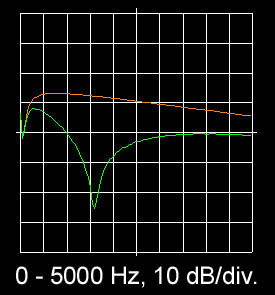
Frequency characteristic (orange line) and side band
suppression (difference between orange and green line).
Side band suppression
The orange line is the frequency characteristic of the receiver. It is quite wide, at 5 kHz, the receiver is approximately 10 dB less sensitive, at 10 kHz approximately 20 dB. The green line is the unwanted side band. The difference between the orange line and the green line is the side band suppression. In my receiver, the band 10140.0 to 10140.1 MHz is mixed to an audio band of 1500 - 1600 Hz. As you can see, the side band suppression in this band is at least 30 dB, despite the simple phase networks! And between 1300 - 1800 Hz still 20 dB. Enough to suppress the noise and therefore to increase the sensitivity with 3 dB But not enough to suppress strong signals. Happily this hardly occurs.
Alignment of the receiver
The tuned antenna circuit at the input is aligned by ear at maximum sensitivity.
The temperature correction is adjusted by warming up and cooling down the receiver with various values of Cx and Cy.
The oscillator level is adjusted by ear at maximum sensitivity. Adjust it a little higher, so that the sensitivity decreases a little. At that point, the suppression of strong AM broadcast signals is better.
The potentiometers P1a and P1b are adjusted with a strong AM signal in the 10 MHz broadcastband for a maximum suppression of AM detection. If possible, use a (simple) AM modulated signal generator.
The two 45 degrees phase networks are adjusted by ear with the trimmers. For that purpose, you do need a signal at the unwanted side band. Adjust the trimmers by ear to maximum suppression of this signal. You have to repeat it a few times, as the settings of each network do influence each other. If you want, you can optimize the side band suppression by changing the values of the resistors in the LF phase networks a little. Then repeat the alignment of the trimmers of the RF phase networks.
Software
You can find much information and software about QRSS on the internet. I do use ARGO of Alberto, I2PHD and Vittorio, IK2CZL. I also do use Spectran, because that has the possibility to listen to the received signals. My laptop does not have the possibility anymore to redirect the input signals directly to the built-in speakers. When you do use the microphone input, switch off the 20 dB boost. If the audio signal is too strong, then you can increse the 10k resistor in the base of T5 to 47k.
For uploading the screenshots, I use Argo Upload by Rik Strobbe (ON7YD). It makes it possible to see via the internet what the receiver at home does receive. So now and then you can look at the live ARGO pictures of my receiver via internet:
grabber.htm, the pictures are refreshed approximately every minute.
Some more results
Although the results are not bad at all, it is not a very good receiver. Quite often, the RF attenuator has to be used to eliminate the AM detection of strong broadcast stations. And the audio band is too wide. For really good results, a better receiver has to be made. But that will be much more complicated!
The sensitivity is good, with ARGO and a dotlength of 3 seconds, a signal of -140 dBm could easily be detected. Also the noise increases when the antenna is connected, even with some RF attenuation. Here below some more results.
VE1VDM with 100mW clearly visible from the other side of the Atlantic Ocean.
With much unaudible, but visible interference from a television receiver!

PA3GFE, received during holidays in Spain (IM98WU).
Index PA2OHH