FREQUENCY STANDARD LOCKED
AT DROITWICH ON 198KHZ
(1997 and 2007)
KLIK HIER VOOR DE NEDERLANDSE VERSIE
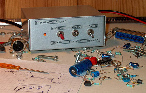
Frequency standard locked at Droitwich on 198 kHz.
And the remaining unused parts of the 1997 version.
OBSOLETE! TRANSMITTER SHUT DOWN (2026)
LISTEN HERE TO THE END!
Frequency standard locked at the longwave broadcast transmitter Droitwich on 198 kHz.
The Droitwich 198 kHz signal is broadcast by a BBC Radio 4 transmitter with a carrier power of 400 kW. The Droitwich station uses rubidium frequency standards and the fractional frequency offset typically observed is less than 10e-11 over a one day averaging period. For nothing we can lock our frequency standard at this very accurate signal!
It is not necessary to make a special receiver, a normal longwave broadcast radio can be used that is tuned on 198 kHz.
The first version was made in 1997. It was quite large, did not have the possibility to calibrate external 10 MHz oscillators and did have much useless electronics for decoding phase modulated data that is also transmitted. Decoding this data never succeeded. That is why in 2007 a smaller and simplier version was made with which also external 10 MHz oscillators can be calibrated.
Block diagram of the frequency standard.
How does it work?
The signal on 198 kHz is received with an ordinary broadcast receiver.
The 10 MHz crystal oscillator is divided by 50 and by 5000 to obtain a 200 kHz and a 2 kHz signaal. The 200 kHz signal is injected into the ferrite antenna of the broadcast radio. Together with the 200 kHz signal, the 198 kHz signal of Droitwich will cause an interference tone of 2 kHz in the loudspeaker. This audio tone of 2 kHz is compared in a phase detector to the 2 kHz signal from the divider. When both 2 kHz signals are not exactly the same, the frequency of the 10 MHz oscillator is controlled.
The 2 kHz audio signal is filtered to suppress speech and music of the broadcast transmitter.
I did need an accurate 1 MHz signal and a 1 kHz signal. The 1 MHz signal is available on an output of one of the dividers, for the 1 kHz signal, the 2 kHz signal is divided by 2. But of course you can choose your own desired frequencies from the outputs of the various dividers.
A normal broadcast receiver is used
to receive the signal on 198 kHz.
Calibration of external 10 MHz oscillators
To calibrate external 10 MHz oscillators, the switch S1 is set to the other position and the internal 10 MHz oscillator is replaced by the external 10 MHz signal. This oscillator is not controlled of course, we have to adjust it ourselfs. On the screen of an oscilloscope the filtered 2 kHz audio signal from the broadcast receiver is displayed. The oscilloscope is triggered by the 1 kHz signal from the dividers. The only thing we have to do now is to adjust the 10 MHz oscillator so that the 2 kHz sine of the audio signal does not move to the left or to the right on the screen. When the sine moves one period in 50 seconds, then the error of the 10 MHz oscillator is approximately 1 Hz.
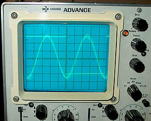
Calibration with an oscilloscope. The audio signal on the screen does
not move to the left or right when the frequency is exactly 10 MHz.
Triggering is done by the 1 kHz signal on channel 2.
Phase modulation of data signals
Unfortunately, we can not use the 198 kHz signal without any problem. It has phase modulation for the transmission of data. You can see that on the screen of the oscilloscope here below. The sine has jitter. This phase modulation has to be suppressed in the loopfilter of the frequency control, otherwise it will disturb the accuracy of the 10 MHz signal of the frequency standard. This can be done by making the loopfilter very slow. By doing so, the control loop will become also less sensitive for radio interference. The loopfilter in the circuit has two positions: a fast one to lock the oscillator and a slow one for when the crystal oscillator is locked.
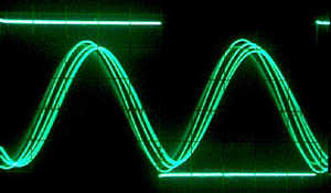
Phase modulated data signals have to be filtered out
in the loopfilter by making it very slow!
The diagram
Right above, you can find the 10 MHz crystal oscillator. With S1 you can select the internal oscillator that is controlled or for an external 10 MHz oscillator that has to be calibrated (adjusted). The internal 10 MHz oscillator is controlled by a varicap BB212 of which only one half is used. Both 74HCT390 are the frequency dividers, it are /2 and /5 dividers. The first divider is a /2 divider because I had once problems with a /5 divider that did not have a perfect square wave as input signal. A disadvantage is that the 1 MHz signal does not have a perfect duty cycle of 50%, because it is an output signal of a /5 divider. But that is not a problem for my application.
The 200 kHz signal is injected into the receiver with a short piece of wire that is mounted close to the ferrite antenna. So not a small loop around or close to the ferrite antenna, but capacitive coupling with a piece of wire, that does work much better.
Diagram
big diagram
The 2 kHz audio signal of the receiver (headphones output) is connected to "lf in" and filtered in 2 active filters with a LM358. What remains is a good useable 2 kHz signal without interference of music and speech. Both filters should have a Q factor of 10 and a gain of 2x2=4x. With the 500 ohm potentiometers, they are exactly adjusted to 2 kHz. The filtered audio signal can be monitored with an oscilloscope by connecting it to "2 kHz audio".
The NAND U1C does make a square wave of the 2 kHz audio signal. U1B is the phase detector. The average value of the output voltage of this phase detector varies between 2.5 V and 5.0 V, perfect to control the varicap. Phase modulation and the 2 kHz square wave are filtered out in the loopfilter.
The loopfilter has two capacitors, one of 10 uF and one of 100 uF. The 10 uF capacitor removes the 2 kHz signal. With S2, the time constant of the filter can be selected for "locking" or "locked" or fast or slow. The loopfilter is too slow with the 1M ohm resistor to get the oscillator locked. When the oscillator is locked, the switch is set to the position "locked" and the 10 MHz oscillator is controlled very slowly. Phase modulation, the 2 kHz square wave and interference do have hardly any influence anymore on the stability in this position of the switch.
The stability of the control loop can be adjusted with the 10k potentiometer in series with the 100 uF capacitor. At 0 ohm, it will take much time before the circuit is stabilized, the frequency goes up and down very long. Also after interferences, stabilization takes a long time. With the potentiometer adjusted to 5k ohm, stabilization goes much quicker.
With the led you can check if the circuit is locked. If not, then the led goes slowly on and off with the frequency difference between both 2 kHz signals.
One NAND is not used, you can use that for example as a buffer after the crystal oscillator when you do need a 10 MHz signal.
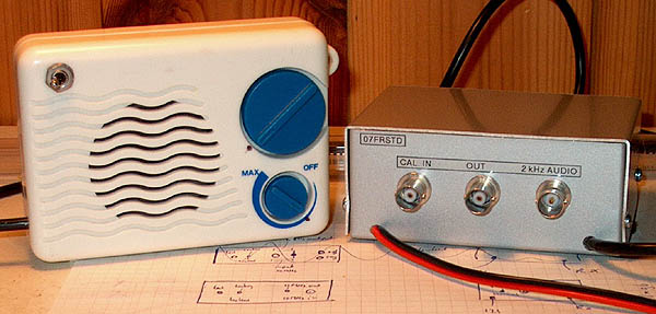
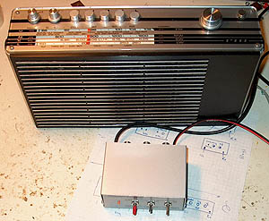
Rear view and modified medium wave
receiver for the reception of Droitwich 198 kHz.
Modified medium wave receiver
The frequency standard worked perfect with the portable radio. But on a flea market, I did buy a small medium wave radio for only 0.50 Euro. It was modified for the reception of Droitwich on 198 kHz by placing capacitors in parallel with the two sections of the tuning capacitor. The 3 volt supply is taken from the 5 volt stabilizer of the frequency standard via two diodes to lower the voltage. The radio is permanently connected with the frequency standard by means of a 4 wire screened cable with a length of 1 meter. Supply, audio and the 200 kHz injection signal go through this cable. The loudspeaker can be switched on or off with a switch.
Results
A good impression of the accuracy can be obtained by comparing the 2 kHz audio signal with the 2 kHz (or 1 kHz) signal from the dividers with an oscilloscope. After that the control loop has stabilized, the variations during a few seconds are approximately 1/50 period. Or, the 2 kHz sine moves 1/50 period to the left or to the right during a few seconds. This is difficult to measure because of the phase modulation. Variations are caused by instability of the 10 MHz oscillator, interference (fading) in the reception and modulation of the transmitter with speech and music. So the frequency error of the 10 MHz oscillator is less than 1 Hz. For us, radio amateurs, more than sufficient!
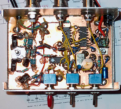
Inside view
For DCF77
Such a frequency standard can also be made for the German standard time and frequency transmitter DCF77 on 77,5 kHz. See here below for the principle that can be used.
Block diagram of a frequency standard locked at DCF77 on 77,5 kHz.
BACK TO INDEX PA2OHH