THE DRAKE SSR1
SHORTWAVE RECEIVER
(1977)

The Drake SSR1 shortwave receiver, serial nr 50241.
Frequency stability due to the Wadley loop!
My first shortwave receiver was this SSR1.
The only receiver I had was an old medium wave receiver with tubes that was modified to receive 80 meter SSB amateurs.
And then just after my schooltime in 1976, this receiver was in the shop, price was reduced considerably as the S-meter was damaged. It was bought from the first money I earned as a soldier. It became my first all band receiver and gave me the chance to discover all the amateurbands. It has been used intensively in the shack, although it is certainly not the best receiver there is.
It was used for the reception of:
- All the amateurbands and to discover their propagation characteristics when becoming a radio amateur.
- For all 2 meter CW QSO's with a 2 meter converter.
- With my first homemade 80, 40, 20 meter transmitter.
- Satellite communications, transmit on 2 meter and receive on 10 meter.
- Popular medium wave broadcast stations.
- Ship to shore traffic.
- Telex reception of amateurs and commercial stations with a Siemens T100 and later with a computer.
- All kinds of other stations which frequencies were mentioned in magazines.
- To check and adjust oscillators while home brewing.
- As a receiver with all kinds of simple QRP transmitters.
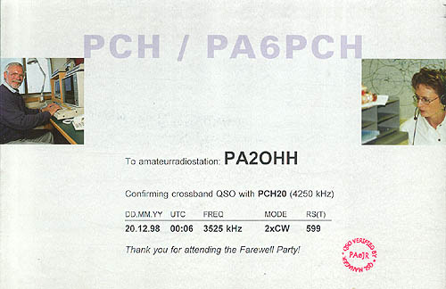
The SSR1 was tuned to 4250 kHz for the QSO with PCH20 during the Farewell party.
I always listened to this CW station when learning CW and later just for fun.
Nice to hear that it transmitted my call... TX was the homemade 80m CW TRX.
Other receivers were more popular.
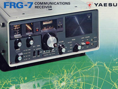
You will not see this receiver so very often. The newer FRG7 was better and more popular. The Racal RA17 was the best receiver with the Wadley principle but had tubes, it had to warm up, was very big and very heavy.
 |
 |
|
The newer FRG7 was better and more popular. |
The Racal RA17 was the best receiver with the
Wadley principle but had tubes |
The SSR1 is electronically seen, for 95% a copy of the popular Barlow Wadley XCR-30 portable. The one knob preselector is replaced by a circuit with switches and a variable capacitor. There are some other minor changes like a RF attenuator and a mains supply. It can even be used with internal batteries and telescopic antenna, just as the Barlow Wadley.
Nowadays, I do not use the SSR1 so often anymore as there are two newer home made receivers here, described somewhere else on this site.
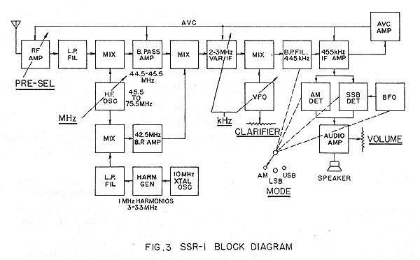
Block diagram of the receiver
Click here for the schematic diagram of the receiver
Explanation of the receiver and the Wadley loop.
In principle, it is a receiver from 2 to 3 MHz. The whole band 0 MHz to 31 MHz is converted to this frequency range in 1 MHz steps.
The Variable Frequency Oscillator (VFO) should be tuned close to 45.5, 46.5, 47.5,......73.5, 74.5, 75.5 MHz, depending on which 1 MHz range between 0 MHz and 31 MHz you want to receive. In passive mixer 1, this desired 1 MHz range is converted to the 1st IF of 45 MHz (44.5 - 45.5 MHz). In passive mixer 2, a harmonic from the 1 MHz harmonic generator is also converted with this VFO signal to a 42.5 MHz amplifier. In the passive mixer 3, this 42.5 MHz signal converts the 1st IF downwards to 2 - 3 MHz, the 1 MHz tuning range of the basic receiver.
If the VFO drifts a little in frequency, the 1st IF and the 42.5 MHz signal do also drift with the same value but the difference (the 2 - 3 MHz signal) will not change! So the stability of the 2 - 3 MHz output signal of passive mixer 3 is only dependent on the stability of the 1 MHz crystal oscillator!
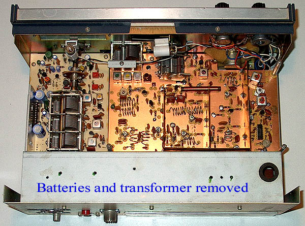
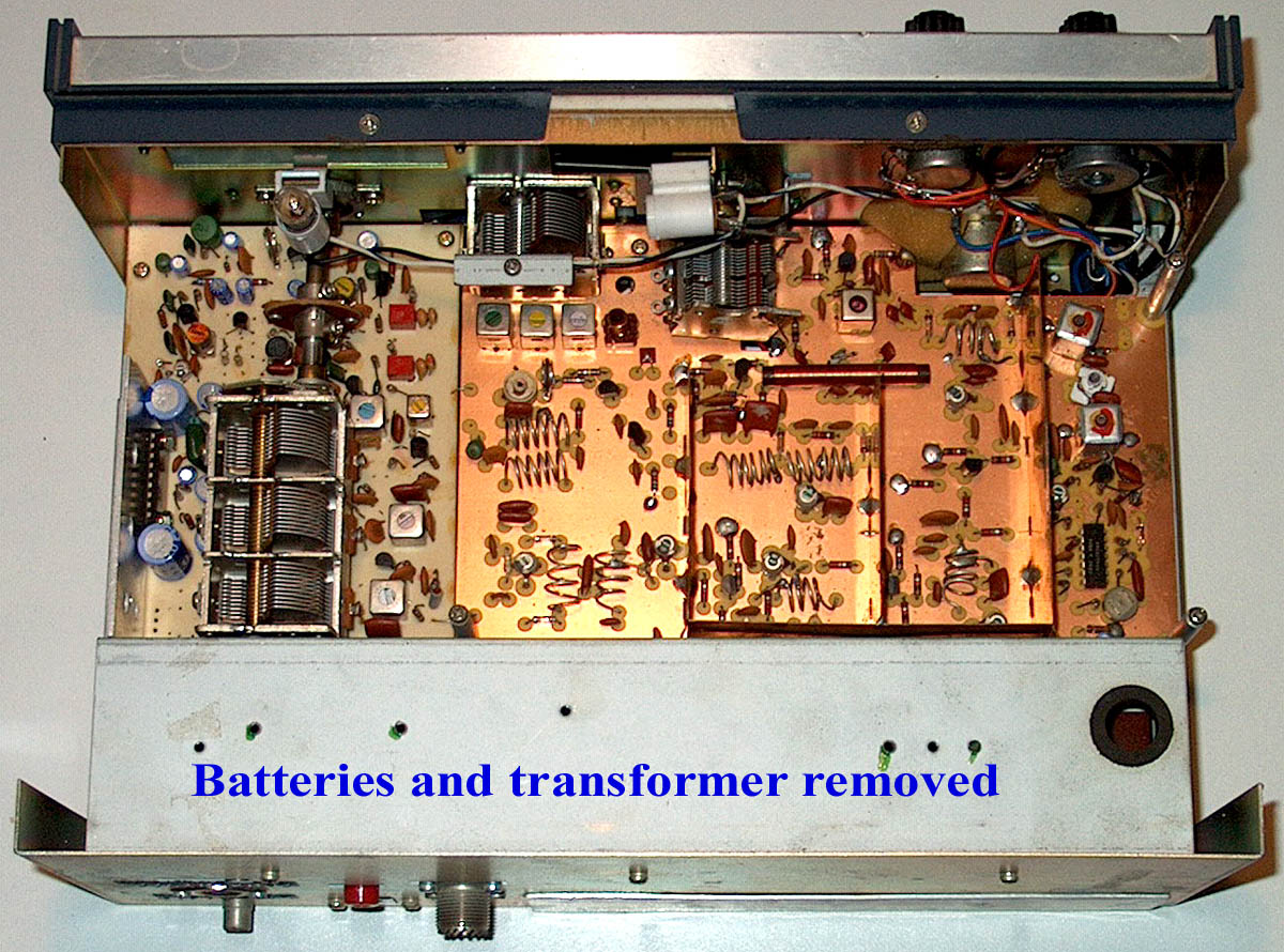
Variable capacitors for the MHz and kHz tuning.
Air coils in the various bandpass filters.
Long wire antenna with the SSR1.
In January during a weekend on the countryside, I could test the SSR1 with a long wire antenna. That was totally different compared to my noisy indoor antenna in the city! It was freezing -6C. It was nice to be outdoors in the freezing cold on the countryside.
The SSR1
Unfortunately, the new SSR1 did not work due to the cold. We found the problem of the SSR1: the 1 MHz comb generator of the SSR1 was an unreliable circuit and had to be readjusted when it was cold.
When the SSR1 was warmed up, it worked very well with the long wire antenna, although.... In the evening, the SSR1 was overloaded by the strong signals from the long wire, especially on 40 meters. And the 20dB attenuator at the rear side of the SSR1 was or too much or not enough. Later, it was replaced by a variable attenuator at the front side of the SSR1. Also the BFO drifted off the frequency when the temperature changed and had to be retuned then. It would be better to use the fine tuning knob to vary the frequency of the BFO instead of the VFO.
A very pleasant evening
Despite all, we had a very pleasant evening listening to all kinds of signals like the amateurbands, 2182 kHz ship traffic and 500 kHz and others.
The sensitivity of the SSR1 is very good. A disadvantage was that the noise in pauses was just as strong as the CW and SSB signals. Therefore, listening was quite tiring. An IF gain control was added later, so that the sensitivity and background noise could be reduced manually.
Long wave CW beacons
I also wanted to try to receive the longwave CW beacons from the Reeds Nautical Almanac. But the SSR1 could not receive any signals below 450 kHz. Later, the SSR1 was modified so that longwave reception was also possible and spotting the CW beacons became one of the hobbies.
Some modifications where necessary, some were just an experiment.
- The sensitivity is very good, 0.1 uV signals are readable. That is necessary for reception with the telescopic whip antenna but not with the long wire antenna. Intermodulation is -40 dBm, that is quite bad. With the long wire antenna, nothing could be received in the evenings at many frequencies like the 40 meter band. The 20 dB RF attenuator at the rear side of the receiver was not really a practical place... So a potentiometer has been added as RF attenuator on the front side. With 20 to 30 dB attenuation, sensitivity is still good enough and suddenly many stations can be heard on frequencies where you do hear all kinds of noisy intermodulation signals without RF attenuator. Happily the receiver has a preselector at the input and not a broadband filter as modern receivers have.
The manufacturer did also discover that the receiver performs better when the RF gain is lower. The emitter resistor is 22 ohm in the diagram but was increased to 100 ohm in my receiver to lower the RF gain.
- The 1 MHz harmonic oscillator was an unstable circuit. That was also the reason that the SSR1 did not work when it was cold. It was a 1 MHz RC oscillator that was synchronized by a 10 MHz crystal oscillator. Very often I had to open the receiver and to adjust it because it did not synchronize anymore. I replaced it by a 1 MHz crystal oscillator.
- The gain of the receiver is so high that the noise between speech pauses or between CW characters was just as loud as the speech or CW signal, also because the AVC works quite fast. A potentiometer was added to reduce the MF gain and the AVC was modified. Reception is much more pleasant and less tiring with lower MF gain.
- The BFO frequency was influenced by strong signals. Strong CW signals were unstable in tone height. It was solved by increasing two resistors from 2k2 to 18k. Later a new mixer with a fet was added to the BFO circuit.
- CW signals sounded not good. I replaced the voltage stabilizer by a 7812 but that was not the cause of the problem. The problem was FM modulation of the VFO by the magnetic field of the power transformer. I removed the power transformer and do use an external 12 volt power supply.
- I changed the clarifier so that it controls the BFO of 455 kHz instead of the VFO. It is possible to tune it to the correct position on the slope of the 455 kHz filter when it drifts a litte.
- With a very simple modification (adding a 1 mH coil), it was also possible to receive the long wave.
- Just as with the Barlow Wadley, a connector was made for an external ferrite rod antenna for the medium wave.
Circuit diagram of the modifications.
Performance
The SSR1 is for 95% a copy of the Barlow Wadley. This receiver was designed for portable use. The SSR1 is however always used as a base station receiver. A problem is that the 1st IF is 1 MHz wide, all kinds of strong signals are present and mixed in the 1st IF and the 1st and 2nd mixer. Therefore, dynamic range and intermodulation are not as good as that of a modern base station receiver with a narrow filter after the 1st mixer. Also the side band suppression is not so good and it does not have a CW filter and noise blanker etc.
Stability is good enough for SSB but not as good as that of a receiver with DDS and PLL technology and not good enough for certain digital modes. That is due to the fact that the VFO and BFO of the 2 - 3 MHz basic receiver are free running L/C oscillators. The analog frequency scale is not as accurate as a digital display.
For serious work, you will need a better receiver. But after the necessary modifications, it was always nice to play with this receiver, it is used very often!
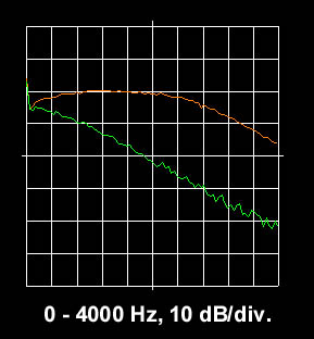
The SSB filter curve (orange) and suppressed sideband (green).
Not so good but good enough for many QSO!
BACK TO INDEX PA2OHH
