SMALL PORTABLE REGENERATIVE RECEIVER
(2003)
KLIK HIER VOOR DE NEDERLANDSE VERSIE
Small portable regenerative receiver
Simple "ultra portable" version for 20, 30 and 40 meters"
If it didn't have so many buttons, it would be a particularly suitable circuit for making a mini receiver with a small battery. To build a small version, a many buttons have to be omitted. After some experimenting with the "large" receiver, it turned out that tuning and regeneration are just enough for SSB and CW. Volume control is done by controlling the regeneration. This is not the case for AM reception, in which case you really cannot do without the LF volume control. The HF controller is not absolutely necessary, I rarely use it and you can always shorten the telescopic antenna in case of overload.
What remains are:
- Tuning (50 pF variable mica capacitor)
- Regeneration
- One switch with center position for 40/30/20 meters
- Headphone plug 3mm, also on/off switch
- Antenna connection (banana plug) for telescopic antenna of 30 cm.
Diagram
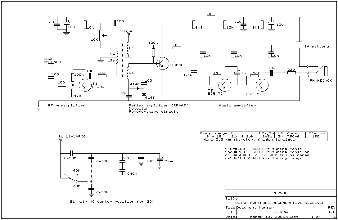
Diagram of the small ultra portable version of the regenerative receiver
The tone control, HF and LF volume controls are therefore omitted, the 0.1 uF capacitor is connected directly to the 1k resistor. The 4k7 ohm resistors are changed to 6k8 due to the slightly higher supply voltage of the 9 volt battery.
T1 is the HF preamplifier and buffer between the regenerative circuit and the 30 cm long antenna. It amplifies the weak signal of the short whip antenna and prevents distortion of the receiver by objects in the vicinity of the antenna. It also blocks the signal from the oscillating receiver towards the antenna, so interference such as my old tube receiver caused to other amateurs is not possible.
T2 does a lot for its money. First it works as an HF amplifier. This amplified signal is rectified by two diodes and the detected audio signal is also amplified by T2, so T2 is not only an HF but also an LF amplifier. Such a circuit is called a reflex circuit and was widely used in the days when transistors were still very expensive.
The regeneration greatly increases amplification and selectivity. For SSB and CW signals it oscillates at the receiving frequency, causing the HF signals to be mixed down to audio frequencies. Due to the negative voltage of the detector when oscillating, the gain of T2 decreases and the regeneration works very smoothly.
The audio amplifier consists of T3 and T4, two transistors BC547C. Use the C type as it provides more gain.
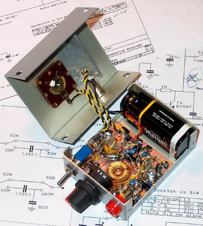
The inside of the receiver
The T50-6 core was later found to be defective. As a new coil shape I took what I first saw lying around: the sawn-off 6 mm plastic shaft of the potentiometer. L1 is approximately 20 to 30 turns, L2a is omitted, L2b is 6 turns and L3 is 3 turns, all wrapped with 0.3mm wire. The wiper of the potentiometer is connected to L2a, to which the HF preamplifier is also connected. The bottom of the potentiometer is no longer connected to ground and therefore floats.
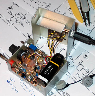
The yellow toroid was later replaced by a coil mounted on a
piece of sawn-off plastic shaft from the potentiometer.
The capacitors Cs and Cp are parallel connected capacitors and trimmers.
Switching on/off is done by plugging in the plug of the ear buds. For this purpose, the minus of the battery is connected to one of the connections of the 3mm chassis part and there is a jumper in the 3mm plug. Besides the fact that no extra space is required for an on/off switch, the big advantage of this is that the receiver cannot be accidentally switched on during transport.
The ear buds are connected in series for a little more audio level. So I use two earphones for my phone, but with good headphones the sound quality is much better.
Antenna
The receiver is very sensitive and you would expect that it can receive many DX stations. But unfortunately that is not the case. You can only use the receiver with short telescope antennas. Signals from full size antennas will seriously overdrive the receiver.
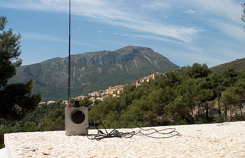
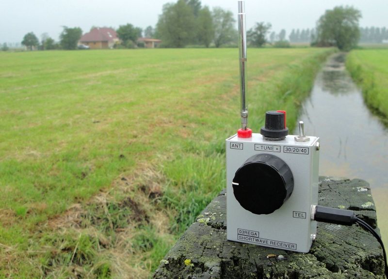
The receiver during warm holidays
Interference due to strong FM broadcast transmitters
At some holiday destinations a lot of interference was caused by strong local FM broadcast stations. This could be solved by placing a 10 pF capacitor between base and emitter and another 10 pF capacitor between the emitter and collector of T1 (the transistor in the HF amplifier). And the 100 ohm resistor at the base of T1 was increased to 330 ohms.
Final
It all seems a bit like very simple technology, but keep in mind that this type of receiver was still a thing of the future a hundred years ago and was considered the "cream of the crop" in 1914. For many years, ocean liners have sailed the world's oceans completely dependent on such a simple regenerative receiver for their contacts.
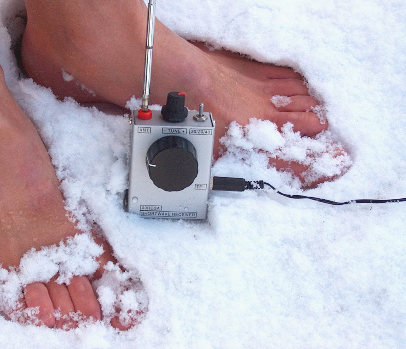
The receiver during cold holidays in the snow! The reception outdoor was much better!
But never go barefoot in the snow when it is colder than -3C to -4C (26F)!
Index PA2OHH